Play all audios:
ABSTRACT Optically induced electroporation (OIE) is a promising microfluidic-based approach for the electroporation of cell membranes. However, previously proposed microfluidic
cell-electroporation devices required tedious sample pre-treatment steps, specifically, periodic media exchange. To enable the use of this OIE process in a practical protocol, we developed a
new design for a microfluidic device that can perform continuous OIE; i.e., it is capable of automatically replacing the culture medium with electroporation buffers. Integrating medium
exchanges on-chip with OIE minimises critical issues such as cell loss and damage, both of which are common in traditional, centrifuge-based approaches. Most importantly, our new system is
suitable for handling small or rare cell populations. Two medium exchange modules, including a micropost array railing structure and a deterministic lateral displacement structure, were
first adopted and optimised for medium exchange and then integrated with the OIE module. The efficacy of these integrated microfluidic systems was demonstrated by transfecting an enhanced
green fluorescent protein (EGFP) plasmid into human embryonic kidney 293T cells, with an efficiency of 8.3%. This result is the highest efficiency reported for any existing OIE-based
microfluidic system. In addition, successful co-transfections of three distinct plasmids (EGFP, DsRed and ECFP) into cells were successfully achieved. Hence, we demonstrated that this system
is capable of automatically performing multiple gene transfections into mammalian cells. SIMILAR CONTENT BEING VIEWED BY OTHERS THE VERSALIVE PLATFORM ENABLES MICROFLUIDIC MAMMALIAN CELL
CULTURE FOR VERSATILE APPLICATIONS Article Open access 29 September 2022 A MICROFLUIDIC TRANSISTOR FOR AUTOMATIC CONTROL OF LIQUIDS Article Open access 25 October 2023 MICROPHYSIOLOGICAL
SYSTEM WITH INTEGRATED SENSORS TO STUDY THE EFFECT OF PULSED ELECTRIC FIELD Article Open access 12 August 2024 INTRODUCTION In the past few decades, single-function microfluidic components
capable of performing specific tasks, such as cell separation1–4, particle/cell focusing5 and cell electroporation6–8, have been thoroughly investigated as stand-alone components in a
variety of microfluidic applications. However, in terms of replacing a traditional clinical laboratory with a single lab-on-a-chip, most of these stand-alone microfluidic components were not
sufficient to address practical problems that require multiple processing steps. For example, in electroporation, mammalian cells must be transferred from the original culture medium into a
specialised electroporation buffer to optimise the electroporation yield9–11. Existing microfluidic electroporation devices are incapable of performing this sample pre-treatment step, and
the inherent advantages of microfluidic lab-on-a-chip systems, such as automation, user friendliness and the reduction of human error, were compromised. Therefore, a real need exists to
develop a microscale total analysis system integrated with different functional microfluidic components to truly leverage the advantages of the aforementioned microfluidic systems. The cell
membrane acts as a barrier to prevent intracellular molecules from randomly being delivered into the interior of cells. Conventional cell electroporation disrupts the integrity of the cell
membrane using a short electrical pulse. Electroporation increases the permeability of the cell membrane to allow chemicals, drugs or foreign DNA chains, to enter into cells for biological
and medical applications. For successful cell electroporation, the target adherent cells also must be trypsinised, washed, and then transferred into a specialised electroporation buffer to
optimise electroporation yield. Furthermore, because of the relatively large size of the electroporation apparatus, a high voltage is commonly used to generate the required electric field
for electroporation. This high voltage and the relatively complicated protocol can easily damage the target cells; this protocol also presents a risk of injury to the operator. Hence, the
cell viability rate after traditional electroporation is typically less than 50% for mammalian cell lines12. Recently, electroporation was integrated into microfluidic devices by using
various types of mechanisms13–17. In comparison to conventional electroporation methods, microfluidic systems have some advantages, including the use of a lower applied electric field, lower
sample and reagent consumption and reduced Joule heating6. However, existing microfluidic electroporation devices with fixed micro-electrodes are incapable of exchanging media in a sample
pre-treatment step. In addition, the fabrication of delicate microelectrodes may also hinder their practical application. Optically induced electroporation (OIE), also known as light-induced
electroporation, is a microfluidic approach for cell electroporation that offers significant flexibility with respect to other methods requiring fixed metal electrodes15. The OIE system
enables the operator to quickly reconfigure the electrode geometries and locations to perform different electroporation applications without having to re-fabricate the entire chip18.
Multiple single cells can be optically targeted for electroporation in parallel by dynamically adjusting the “virtual electrodes” projected by the digitally controlled light patterns. This
precision control of the electrode leaves the other cells unaffected. External substances, such as fluorescent dyes and genes, have been successfully transferred into mammalian cells using
this method15,19. However, a proper electroporation buffer (such as a 0.2 M sucrose solution) is commonly used to generate sufficient transmembrane potentials on cells for OIE19. Therefore,
the re-suspended cells must be centrifuged in advance to replace the original culture medium with the proper electroporation buffer. Thus, this centrifuging step makes cell electroporation a
complicated process. Microfluidic-based devices for cell separation can be divided into two categories: active or passive approaches. Active microfluidic devices require an external force
to control fluid transfer and for cell separation. For example, we previously reported a microfiltering structure to collect cells for the subsequent optically induced cell separation
process20. Up to 96.2% of the live cells loaded into the microfluidic device were successfully recovered. However, this device required a precision micropump for flow control. Alternatively,
several passive microfluidic approaches to sort and to manipulate cells have been demonstrated previously. For example, a deterministic lateral displacement (DLD) structure is a promising
microfluidic technique to separate particles and cells based on their sizes, shape and deformability21–23. DLD is a passive, hydrodynamics-based particle-sorting technique that consists of a
symmetric array of micro-posts22,24. The hydrodynamic interaction between particles and the microstructures enables the separation of particles with different sizes. A larger particle is
deflected at a specific angle and then transferred to another flow stream. By contrast, a smaller particle is not affected by these interactions and hence is not laterally displaced. In
addition, DLD is able to steer, refract and focus streams of biomaterials and has been implemented in various biomedical applications23,25–30. A micro-post array railing (μPAR) structure is
another passive, hydrodynamics-based particle-sorting technique31. The μPAR structure consists of an array of square micro-posts that are tilted at a specific angle with respect to the fluid
flow direction. The gaps between micro-posts are smaller than the suspended target particles or cells and could therefore guide them into discrete, adjacent laminar flow streams. This
structure had been demonstrated to automatically perform molecular synthesis processes on polystyrene microbead substrates while simultaneously mixing suspended cells with discrete, parallel
flow streams31,32. Note that the DLD or µPAR microstructures were originally demonstrated for the separation of particles or cells. In this work, DLD or µPAR microstructures have been
adopted to guide cells into a certain direction so that medium exchange could be performed continuously. Herein, a novel microfluidic device was developed that combines both OIE and medium
exchange functions into an integrated system. The continuous medium exchange and electroporation of the cells is performed by the medium exchange modules consisting of µPAR or DLD structures
and the OIE module, respectively. This system enables a completely integrated cell electroporation workflow. Finally, single or co-transfection of three types of fluorescently labelled
plasmids into HEK 293T cells was successfully demonstrated using this OIE microfluidic system. These results show that this microfluidic system is a promising tool for genetic engineering.
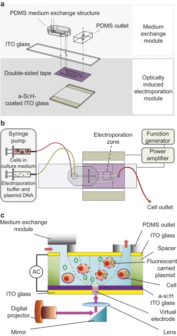
MATERIALS AND METHODS DESIGN OF THE INTEGRATED MICROFLUIDIC SYSTEM The developed integrated microfluidic system has two modules connected in series: the medium exchange and the OIE modules,
as schematically shown in Figure 1. First, the re-suspended cells in the original culture medium were transferred into the electroporation buffer by using one of the passive medium exchange
modules. Next, the electroporation buffer carrying the cells flows into the OIE module, where electroporation occurs. As schematically shown in Figure 1a, the continuously flowing, passive
medium exchange module consisted of a patterned polydimethylsiloxane (PDMS) structure bonded to a layer of indium-tin-oxide (ITO) glass substrate. The OIE module was formed by bonding the
top layer of ITO glass to a bottom layer of hydrogen-rich amorphous-silicon (a-Si:H)-coated ITO glass with double-sided tape patterned by a CO2 laser. The modules were connected via through
holes drilled at the interface between the two modules while the processed fluid was collected from the single PDMS outlet located at the top of the integrated device. EXPERIMENTAL SETUP An
illustration of the OIE chip is shown in Figure 1b. The developed chip was mounted on an upright fluorescence microscope (BX43, Olympus Co., Japan) that allowed for real-time observation
using a charge-coupled device (CCD) camera (Evolution VF, Media Cybernetics, Inc., USA). Two fluid streams of (1) medium with cells and (2) electroporation buffer with fluorescently labelled
plasmids were continuously injected into the microfluidic chip using two syringe pumps (KDS-270, KD Scientific, USA). Note that double-side tape was used as a spacer. Cells, reagents and
buffers were first introduced from the through-hole of the PDMS inlet, and then the entire process, i.e., medium exchange and OIE was performed automatically. The position of the virtual
electrodes was determined by the projected light pattern, which was generated by the digital projector. The re-suspended cells were transferred from the culture media into the flowing
electroporation buffer using DLD or μPAR structures. Figure 1c shows a cross-sectional view of the device that describes the working principle of the optically induced gene transfection. The
target cell and fluorescently labelled plasmid were transported via the electroporation buffer into the lower OIE module. A digital projector (PLC-XU106, SANYO Electric Co., Japan)
illuminated a light spot onto the a-Si:H layer, which acted as a virtual electrode in the electroporation zone. The alternating-current (AC) voltage was generated by a function generator
(AFG-2125, Good Will Instrument Co., Ltd., Taibei) and amplified by a power amplifier (HA-405, PINTEK, New Taipei City). This established an AC electric field between the top and bottom ITO
layers. Next, the fluorescently labelled plasmids were electroporated into the target cell. The output voltage was monitored using an oscilloscope (GDS-1102-U, Good Will Instrument Co.,
Kaohsiung). Finally, the electroporated cells were collected at the outlet and cultured for further analysis. DESIGN OF MEDIUM EXCHANGE MODULES: DLD AND ΜPAR To transfer the cells from the
original culture medium into the electroporation buffer, the culture medium with suspended cells was injected into the outer flow. The target cell was guided to the central stream of the
electroporation buffer by the DLD structures (Figure 2a). The DLD design parameters, _λ_ = 60 µm, _ε_ = 0.05, gap = 30 µm, correspond to a critical particle diameter (Dc) of ~9 µm and the
scanning electron microscope (SEM) image of the DLD microstructure is presented in Figure 2b. Therefore, any target HEK 293T cells greater than 9 µm in diameter fell into the “bump mode”
category and could be theoretically transferred into the buffer stream22. For the µPAR structure, the re-suspended cells in the outer streams were guided into the centre of the
electroporation buffer stream by the µPAR structure (Figure 2c). Next, the cells were electroporated using OIE. The µPAR structure consisted of tilted arrays of rectangular micro-posts with
gaps smaller than the diameter of the cells. The length of the sides of the micro-posts was 20 µm, and the gap between micro-posts was 10 µm. The tilt angle of the arrays with respect to the
fluid flow, _α_, was 1°, and the SEM image of the µPAR microstructure is presented in Figure 2d. FABRICATION OF THE MEDIUM EXCHANGE MODULES The medium exchange modules were micro-fabricated
by bonding PDMS fluid channels onto the non-conducting side of the ITO glass substrate. A 50 µm thick layer of negative photoresist SU-8 3050 (MicroChem Corp., USA) was
photolithographically patterned as a mould and was used to replicate the inverse structure in PDMS. First, a bare silicon wafer substrate was rinsed with double-distilled water (ddH2O) and
then sonicated for 5 min in acetone to detach any particles from the surface. Next, the treated wafer was rinsed with ddH2O and then air dried. Afterwards, the wafer was treated with a
buffered-oxide-etch (BOE) reagent, rinsed with ddH2O and then dried again. Following the BOE treatment, the wafer was placed on a hotplate at 150 °C for 5 min to dehydrate the surface. After
this substrate pre-treatment, the wafer was cooled down to room temperature, and then a layer of SU-8 50 with a thickness of 50 µm was spin-coated onto the surface using a spin-coater
(200F, Filmtronics, USA). Next, the SU-8 was soft-baked at 65 °C for 6 min and then at 95 °C for 20 min to evaporate the solvent prior to exposure. Next, the wafer was cooled down to room
temperature prior to exposure. The ultraviolet light exposure dosage for SU-8 was 250 mJ cm−2. A two-step post exposure bake was performed immediately after the exposure at 65 °C for 1 min
and then at 95 °C for 5 min. Finally, the developed pattern was rinsed with isopropyl alcohol and dried. As a final step, the wafer and SU-8 mould were placed on a hot plate at 175 °C for 4
hours to enhance the strength of the structure. This structure served as a negative mould for the PDMS. For casting the PDMS, an elastomer (Sylgard 184A silicon elastomer, Dow Corning, USA)
and a curing agent (Sylgard 184B elastomer curing agent, Dow Corning, USA) were well mixed in a 10:1 ratio by weight, poured onto the SU-8 mould and then cured at 80 °C over 2 h to form the
DLD and µPAR microstructures for medium exchange. FABRICATION OF THE OIE MODULE AND THE INTEGRATION OF THE TWO MODULES The OIE channel was patterned on a piece of double-sided tape (50 µm in
height; Tesa Tape, Inc., USA) by using a laser-cutting machine (VersaLASER VL-200, Universal Laser Systems, Inc., USA). The patterned tape was attached to the a-Si:H coated ITO glass, and
then through-holes were drilled to form an OIE module. Finally, the drilled holes in the PDMS medium exchange structure and the PDMS outlet were aligned and bonded onto the top surface of
the ITO glass via oxygen plasma treatment. PREPARATION OF HUMAN EMBRYONIC KIDNEY 293T (HEK 293T) CELLS AND ELECTROPORATION BUFFER Human embryonic kidney cells (HEK 293T, ATCC® CRL-11268TM)
were provided by the Institute of Microbiology and Immunology, College of Medicine, Chung Shan Medical University, Taichung and cultured in Dulbecco's Modified Eagle Medium (DMEM),
which contained 10% fetal bovine serum (Sigma Co., USA), 2 mM of L-glutamine (Sigma Co., USA) and 1% penicillin/streptomycin. The monolayer of cells was trypsinised with 1x trypsin-EDTA
(Sigma Co., USA) and then re-suspended in DMEM, yielding a final concentration of 106 cells ml−1. The pEGFP-N1 (4.7 kp), pDsRED (4.1 kp) and pECFP (4.1 kp) plasmids were provided by the
Institute of Biomedical Sciences, National Sun Yat-Sen University, Kaohsiung. Note that the three fluorescently labelled plasmid DNAs were extracted with NucleoBond® Xtra Midi kits (MACHEREY
NAGEL GmbH & Co, Germany), following the protocols in the user's manual. These extracted plasmid DNAs were re-suspended in 0.2 M sucrose (Sigma Co., USA) at a final concentration
of 2 μg ml−1. OIE PARAMETERS The optimised experimental parameters for the continuous medium exchange and the OIE experiment are presented in Table 1, which were based on the OIE simulations
and the practical operating limits of the instrumentation. Specifically, the applied AC frequency was designated to be just below the value that would cause hydrolysis in the OIE channel,
and the light irradiance and light spot size were both set at stable conditions near the upper limits of the optical system. RESULTS EXCHANGE EFFICIENCY OF THE MEDIUM EXCHANGE MODULES Tests
on the medium exchange modules were first performed to ensure the successful performance of the proposed device. The deflection of the cellular trajectory was observed in the DLD continuous
medium exchange module (Figure 3a). The HEK 293T cells in the DLD structure were in the “bumping mode”, where the trajectory of the cells was inclined at a specific tilt angle towards the
centre of the channel, resulting in an overall lateral displacement that shifted the cells from the outer flow to the centre flow of the electroporation buffer. Note that the medium and
buffer flows were injected using syringe pumps at the same flow rates of 25 µl min−1. For the medium exchange module with µPAR structures, the deflection in flow trajectory was also
observed. The cells were guided toward the centre stream of the electroporation buffer by the micro-post arrays (Figure 3b). The continuous flows of cell culture medium and electroporation
buffer streams were injected using syringe pumps set at the same flow rates of 70 µl min−1. To evaluate the performance of the two medium exchange modules, HEK 293T cells suspended in the
culture medium and the electroporation buffer (0.2 M sucrose) were injected into the modules. The cells were collected from the three outlets of each module (one central outlet and two side
outlets). For the DLD medium exchange module, the fluids were injected by the syringe pumps at the same corresponding volumetric flow rates, ranging from 30 to 90 µl min−1. Alternatively,
the fluids in the µPAR medium exchange module were driven by using a vacuum pump at the outlets with equally applied gauge pressures, ranging from −100 to −300 mmHg. The exchange efficiency
was calculated by dividing the number of cells collected from the central outlet by the number of total cells collected from all three outlets (as shown in Equation (1)). (1) Exchange
efficiency = Cells collected from the central oulet Total number of collected cells × 100 % The experimental results showed that the exchange efficiency was higher for the proposed µPAR
module than the DLD module at different fluid flow rates. For the DLD medium exchange module, the exchange efficiency increased with increasing flow rate and saturated at high flow rates
(Figure 4a). The highest exchange efficiency of 33.7% was observed at a volume flow rate of 90 µl min−1 (Figure 4a). In the µPAR medium exchange module, the exchange efficiency also
increased with increasing flow rates. The stronger the vacuum suction, the faster the fluid flow and the higher the exchange efficiency. Saturation was also observed at higher flow rates
(Figure 4b). The maximum value of the exchange efficiency for the µPAR medium exchange module was measured to be 79.5% at a gauge pressure of −300 mmHg (Figure 4b). Note that three
consecutive experiments were performed for each test. Conventionally, μPAR and DLD microstructures were only used to separate mixed particles or cells in single buffer, depending on the size
of particles1,31. However, μPAR and DLD were used to perform the medium exchange in this study, which represents the first time that these similar microstructures were used for medium
exchange. THE EFFECT OF THE SIZE AND THE PHOTOCONDUCTIVITY OF THE VIRTUAL ELECTRODE ON THE TRANSMEMBRANE POTENTIAL The effects of three independent parameters on the cell transmembrane
potential, including the spot diameter of the illuminated pattern, the applied AC frequency and the photoconductivity of the a-Si:H film, were considered when inducing electroporation.
Commercially available software (COMSOL Multiphysics, USA) was used to numerically simulate the cell transmembrane potential induced by the virtual electrode. To better understand the
relationship between these parameters and the maximum transmembrane potential, the following parameters were used: the relative spot diameter, defined as the full width at half maximum
divided by the cell diameter (12 µm), and the relative photoconductivity, defined as the a-Si:H photoconductivity divided by the conductivity of the medium outside the cell. The results of
the numerical simulation showed that the maximum induced transmembrane potential generally increased with the increasing relative spot diameter and the relative photoconductivity. The
dependence of the transmembrane potential on the relative spot diameter can be determined from the pattern of the voltage distribution under different spot diameters (Figure 5a), where the
relative photoconductivity and the applied AC frequency were 0.1 and 1 kHz, respectively. For smaller spot diameters, the cell at the centre of the channel was less affected by the gradient
of the voltage distribution across the electroporation buffer. As the diameter of the “virtual electrode” increased, the area of the voltage gradient expanded and reached the cell, inducing
a larger transmembrane potential across the cell membrane. To determine the maximum transmembrane potential with respect to the driving frequency, the spot size and the photoconductivity, a
simultaneous parametric sweep of all three variables was performed. The size of the black spheres represented the value of the maximum transmembrane potential under each condition (Figure
5b). In general, the induced transmembrane potential at a certain applied peak-to-peak voltage could be maximised by increasing the relative photoconductivity and the relative spot diameter,
and decreasing the applied AC frequency. TRANSFECTION OF PLASMID DNA USING THE INTEGRATED MICROFLUIDIC SYSTEM In our previous work33, fluorescence dyes (propidium iodide, PI and calcein
acetoxymethyl ester, CaAM) were used to measure the electroporation efficiency when μPAR microstructures were used to perform the medium exchange. However, using fluorescent dyes to
determine the electroporation efficiency is considered to be indirect evidence. In conventional electroporation or transfection experiments, plasmid DNA is commonly used to demonstrate the
extent of gene transfection while developing novel methods or new systems34. Therefore, the fluorescence-carrying plasmid DNA was used to determine the efficiency of electroporation in this
study. Transfection of a pEGFP-N1 plasmid DNA was conducted to demonstrate the successful integration of the two modules. The use of HEK 293T cells, human embryonic kidney cells, has been
commonly reported for gene transfection and was used as a guideline template for many transfection kits (e.g. lipofectamine, Thermo Fisher Scientific Inc.)32. HEK 293T cells were
re-suspended in a culture medium and the electroporation buffer (0.2 M sucrose) containing the plasmid DNA was injected into the complete integrated system. The 293T cells in the culture
medium were transferred into the central stream of the electroporation buffer by the DLD medium exchange module and then were transported to the OIE module for electroporation. The cells
then flowed into the OIE zone, where the applied electric field induces a sufficient transmembrane potential across the cell for electroporation. The processing of 250 µl of culture medium
with suspended cells at a flow rate of 25 µl min−1 took approximately 10 min. The fluorescence intensity of the expressed EGFP plasmid was measured using a flow cytometer (BD ACCURI C6,
USA). The expressed percentage of green fluorescence signal increased with the increasing applied peak-to-peak voltage in the OIE module. The highest efficiency of 8.3% occurred at 40 Vpp.
This efficiency is the highest transfection efficiency ever demonstrated among existing OIE methods19. Note that the light irradiance on the OIE zone was 1.5 W cm−2 and the volumetric flow
rates of both liquid streams were 25 µl min−1. In addition to single DNA transfection, co-transfection of three plasmid DNAs into a single cell was also determined by the developed system,
as shown in Figure 6a and 6d. The co-transfection into HEK 293T cells of pDsRED, pECFP and pEGFP-N1, which were red, blue and green fluorescently labelled plasmids, respectively, were
successfully electroporated by using the DLD-OIE system (Figure 6b–d) and the µPAR-OIE system (Figure 6e–h), as verified by using an upright fluorescence microscope (BX43, Olympus Co.,
Japan) after 24 hours in culture. Note that the light irradiance on the OIE zone was 1.5 W cm−2. The applied voltage was 40 Vpp at a frequency of 20 kHz. These images demonstrated that the
novel microfluidic system successfully combined continuous medium exchange and optically electroporation modules to automatically perform the entire protocol for the transfection of
exogenous molecules from re-suspended cells to electroporation. Note that all cells were viable after the transfection process was completed. DISCUSSION Cell debris was observed in the
channel and between the micro-posts of the µPAR medium exchange module, as well as in the DLD medium exchange module. This debris can reduce the number of cells collected at the central
outlet of the medium exchange module and compromise the medium exchange efficiency. The formation of the debris from the disruption of these cells could result from the high fluidic shear
stresses experienced during the medium exchange process at high flow rates, where the cells are forced to change their direction in the fluid flow after sliding through the microposts of the
µPAR structures. The average fluid velocity in this study (approximately 6 mm s−1 at a volume flow rate of 90 μl min−1) was two to three times higher than the fluid velocity used in the
previous study with biological cells (2.3 mm s−1) where the observed railing failure rates (RFRs) were equivalent to 0%, i.e., no clogging of cells was observed31. However, reducing the
fluid velocity would compromise the throughput of the medium exchange system and the overall transfection efficiency of the integrated microfluidic system. Therefore, a more thorough study
of the relationship between shear-induced cell lysis and the fluid velocity in the medium exchange modules is required in the future. Another factor reducing the cell recovery rate was the
cell clogging observed in the µPAR or DLD structures during experiments. In the µPAR medium exchange module, although the 10 μm gaps between microposts were smaller than the cell diameter
(13 μm on average for HEK 293T cells), a certain percentage of the cells were still able to squeeze through the gaps or were trapped between posts due to their deformability, hence affecting
the module performance. It is believed that the percentage of micropost gaps clogged by cells was inversely related to the volume flow rate. As the cells gained more momentum in the
direction of the fluid along the channel, they were less affected by the fluid flowing through the gaps between the microposts, thereby reducing the possibility of being squeezed through or
trapped in the gaps. The DLD structure, when compared with the µPAR structure, is ideally a clog-free cell separation method because the gaps are larger than the diameter of the cell of
interest. However, factors such as variations in cell sizes, clumps of cells adhering together due to poor cell handling before the experiment, and insufficient surface pretreatment and
modification to reduce cell adhesion could still result in the clogging of cells, as observed in the medium exchange experiments. Importantly, the cells were always filtered past a cell mesh
filter before being injected into the device to ensure that only single cells were allowed into the module. Otherwise, lumps of multiple cells would be trapped in the gaps, thus defeating
the purpose of the DLD structure. In addition, a protein-blocking surface treatment was required to prevent the cells from adhering to the PDMS surface because any attached cells would alter
the hydrodynamic paths, and therefore adversely affect the cell recovery rate of the medium exchange module. In this study, we demonstrated a new microfluidic OIE system integrated with the
continuous medium exchange module to address the sample pre-treatment problem. The integrated microfluidic system was composed of two separated modules: the continuous medium exchange
module (to automatically transfer the re-suspended cells into the specific electroporation buffer) and the OIE module (for cell electroporation). Two microfluidic cell separation methods,
DLD and μPAR, were used in the design of two continuous medium exchange modules. Experimental results suggest that the μPAR structure outperformed the DLD structure in terms of exchange
efficiency. This developed microfluidic system is the first integrated microfluidic optical electroporation system capable of performing continuous medium exchange on one device. Compared
with previous work using micro-filtering devices for medium exchange, the current work allows for continuous separation of cells and medium exchange, thus increasing the throughput of the
developed device20. DNA transfection can be performed using microelectrodes. However, microelectrodes require tedious fabrication processes. Both microelectrodes and optically assisted
dielectrophoresis on a microsystem could be used for DNA transfection19. These approaches require the tested cells to be transfected with extracellular nucleic acids in a “static” situation.
Our results represent the first time that the tested cells could be automatically transferred to a suitable transfection buffer and that DNA transfection could be performed in a continuous
“flow-through” format. The throughput of the developed system depended on the volumetric flow rate of the culture medium and the concentration of the cells. For example, the throughput of
the integrated microfluidic system was 2.5 × 10⁴ cells per minute for the medium with 106 cells ml−1 at a volume flow rate of 25 μl min−1, assuming no cell loss in the system. The throughput
of the system could be increased by adjusting the flow rate and the cell concentration. However, the higher volumetric flow rate would reduce the electroporation duration in the OIE module
and may affect the overall electroporation efficiency. Furthermore, the developed device achieved the highest gene transfection efficiency of 8.3% for EGFP, among all current OIE methods14.
Moreover, co-transfection of multiple fluorescently labelled plasmids (EGFP, DsRed and ECFP) was confirmed. These results indicate that the developed device has great potential for use in
various electroporation-related biological applications, such as creating induced pluripotent stem cells (iPSCs) and for gene therapy. REFERENCES * Hou HW, Bhagat AAS, Lee WC et al.
Microfluidic devices for blood fractionation. _Micromachines_ 2011; 2: 319–343. Article Google Scholar * Lenshof A, Laurell T . Continuous separation of cells and particles in microfluidic
system. _Chemical Society Reviews_ 2010; 39: 1203–1217. Article Google Scholar * Bhagat AAS, Bow H, Hou HW et al. Microfluidics for cell separation. _Medical & Biological Engineering
& Computing_ 2010; 48: 999–1014. Article Google Scholar * Pamme N . Continuous flow separations in microfluidic devices. _Lab on a Chip_ 2007; 7: 1644–1659. Article Google Scholar *
Xuan X, Zhu J, Church C . Particle focusing in microfluidic devices. _Microfluid and nanofluid_ 2010; 9: 1–16. Article Google Scholar * Movahed S, Li D . Microfluidics cell
electroporation. _Microfluid and nanofluid_ 2011; 10: 703–734. Article Google Scholar * Kim J, Hwang I, Britan D et al. Microfluidic approaches for gene delivery and gene therapy. _Lab on
a Chip_ 2011; 11: 3941–3948. Article Google Scholar * Wang M, Orwar O, Olofsson J et al. Single-cell electroporation. _Analytical and Bioanalytical Chemistry_ 2010; 397: 3235–3248. Article
Google Scholar * Potter H, Heller R . Transfection by electroporation. _Current Protocols in Neuroscience_ 2011; Appendix 1: 1E. * Jordan ET, Collins M, Terefe J et al. Optimizing
electroporation conditions in primary and other difficult-to-transfect cells. _Journal of Biomolecular Techniques_ 2008; 19: 328–334. Google Scholar * Pucihar G, Kotnik T, Kandušer M et al.
The influence of medium conductivity on electropermeabilization and survival of cells in vitro. _Bioelectrochemistry_ 2001; 54: 107–115. Article Google Scholar * Lee WG, Demirci U,
Khademhosseini A . Microscale electroporation: Challenges and perspectives for clinical applications. _Integrative Biology_ 2009; 1: 242–251. Article Google Scholar * Fei Z, Wang S, Xie Y
et al. Gene transfection of mammalian cells using membrane sandwich electroporation. _Analytical Chemistry_ 2007; 79: 5719–5722. Article Google Scholar * Valero A, Post JN, van
Nieuwkasteele JW et al. Gene transfer and protein dynamics in stem cells using single cell electroporation in a microfluidic device. _Lab on a Chip_ 2008; 8: 62–67. Article Google Scholar
* Valley JK, Neale S, Hsu HY et al. Parallel single-cell light-induced electroporation and dielectrophoretic manipulation. _Lab on a Chip_ 2009; 9: 1714–1720. Article Google Scholar * Wang
HY, Lu C . Electroporation of mammalian cells in a microfluidic channel with geometric variation. _Analytical Chemistry_ 2006; 78: 5158–5164. Article Google Scholar * Zhan Y, Wang J, Bao
N et al. Electroporation of cells in microfluidic droplets. _Analytical Chemistry_ 2009; 81: 2027–2031. Article Google Scholar * Lin YH, Lee GB . An optically induced cell lysis device
using dielectrophoresis. _Applied Physics Letters_ 2009; 94: 033901. Article Google Scholar * Wang CH, Lee YH, Kuo HT et al. Dielectrophoretically-assisted electroporation using
light-activated virtual microelectrodes for multiple DNA transfection. _Lab on a Chip_ 2014; 14: 592–601. Article Google Scholar * Lee GB, Wu HC, Yang PF et al. Optically induced
dielectropheresis sorting with automated medium exchange in an integrated optofluidic device resulting in higher cell viability. _Lab on a Chip_ 2014; 14: 2837–2843. Article Google Scholar
* Beech JP, Holm SH, Adolfsson K et al. Sorting cells by size, shape and deformability. _Lab on a Chip_ 2012; 12: 1048–1051. Article Google Scholar * Huang LR, Cox EC, Austin RH et al.
Continuous particle separation through deterministic lateral displacement. _Science_ 2004; 304: 987–990. Article Google Scholar * Holm SH, Beech JP, Barrett MP et al. Separation of
parasites from human blood using deterministic lateral displacement. _Lab on a Chip_ 2011; 11: 1326–1332. Article Google Scholar * Inglis DW, Davis JA, Austin RH et al. Critical particle
size for fractionation by deterministic lateral displacement. _Lab on a Chip_ 2006; 6: 655–658. Article Google Scholar * Davis JA, Inglis DW, Morton KJ et al. Deterministic hydrodynamics:
Taking blood apart. _Proceedings of the National Academy of Sciences of the United States of America PNAS, Proceedings of the National Academy of Sciences_ 2006; 103: 14779–14784. Google
Scholar * Morton KJ, Loutherback K, Inglis DW et al. Hydrodynamic metamaterials: Microfabricated arrays to steer, refract, and focus streams of biomaterials. _Proceedings of the National
Academy of Sciences of the United States of America PNAS, Proceedings of the National Academy of Sciences_ 2008; 105: 7434–7438. Google Scholar * Green JV, Radisic M, Murthy SK .
Deterministic lateral displacement as a means to enrich large cells for tissue engineering. _Analytical Chemistry_ 2009; 81: 9178–9182. Article Google Scholar * David WI, Megan L, Robert
EN . Scaling deterministic lateral displacement arrays for high throughput and dilution-free enrichment of leukocytes. _Journal of Micromechanics and Microengineering_ 2011; 21: 054024.
Article Google Scholar * Liu Z, Huang F, Du J et al. Rapid isolation of cancer cells using microfluidic deterministic lateral displacement structure. _Biomicrofluidics_ 2013; 7: 011801.
Article Google Scholar * Karabacak NM, Spuhler PS, Fachin F et al. Microfluidic, marker-free isolation of circulating tumor cells from blood samples. _Nature Protocols_ 2014; 9: 694–710.
Article Google Scholar * Sochol RD, Li S, Lee LP et al. Continuous flow multi-stage microfluidic reactors via hydrodynamic microparticle railing. _Lab on a Chip_ 2012; 12: 4168–4177.
Article Google Scholar * Sochol RD, Corbett D, Hesse S et al. Dual-mode hydrodynamic railing and arraying of microparticles for multi-stage signal detection in continuous flow biochemical
microprocessors. _Lab on a Chip_ 2014; 14: 1405–1409. Article Google Scholar * Chang CJ, Lu MY, Lee GB . A continuous optically-induced cell electroporation device with on-chip medium
exchange mechanisms. IEEE 27th International Conference on Micro Electro Mechanical Systems (IEEE MEMS); 26–30 Jan 2014; San Francisco, CA, USA; 2014: 234–237. * Le Gac S, van den Berg A .
Single cell electroporation using microfluidic devices. _Methods in Molecular Biology_ 2012; 853: 65–82. Article Google Scholar Download references ACKNOWLEDGEMENTS The authors gratefully
acknowledge the financial support provided to this study by “the National Science Council in Taiwan (NSC102-2218-E-007-001)”. Partial financial support from the “Towards a World-Class
University” Project is also greatly appreciated. The authors also thank Dr. Ming-Shiou Jan (Institute of Microbiology and Immunology, College of Medicine, Chung Shan Medical University,
Taichung) and Dr. Kuang-Hung Cheng (The Institute of Bio-medical Sciences, National Sun Yat-Sen University, Kaohsiung) for providing the cell line (HEK 293T) and the fluorescently labelled
plasmids (pEGFP-N1, pDsRED and pECFP), respectively. AUTHOR INFORMATION AUTHORS AND AFFILIATIONS * Department of Power Mechanical Engineering, National Tsing Hua University, Hsinchu, 30013
Gwo-Bin Lee, Chia-Jung Chang, Chih-Hung Wang, Ming-Yu Lu & Yen-Yi Luo * Institute of Biomedical Engineering, National Tsing Hua University, Hsinchu, 30013 Gwo-Bin Lee * Institute of
NanoEngineering and Microsystems, National Tsing Hua University, Hsinchu, 30013 Gwo-Bin Lee Authors * Gwo-Bin Lee View author publications You can also search for this author inPubMed Google
Scholar * Chia-Jung Chang View author publications You can also search for this author inPubMed Google Scholar * Chih-Hung Wang View author publications You can also search for this author
inPubMed Google Scholar * Ming-Yu Lu View author publications You can also search for this author inPubMed Google Scholar * Yen-Yi Luo View author publications You can also search for this
author inPubMed Google Scholar CORRESPONDING AUTHOR Correspondence to Gwo-Bin Lee. ETHICS DECLARATIONS COMPETING INTERESTS The authors declare no conflict of interest. RIGHTS AND PERMISSIONS
This license allows readers to copy, distribute and transmit the Contribution as long as it attributed back to the author. Readers may not alter, transform or build upon the Contribution,
or use the article for commercial purposes. Please read the full license for further details at - http://creativecommons.org/licenses/by-nc-nd/4.0/ Reprints and permissions ABOUT THIS
ARTICLE CITE THIS ARTICLE Lee, GB., Chang, CJ., Wang, CH. _et al._ Continuous medium exchange and optically induced electroporation of cells in an integrated microfluidic system. _Microsyst
Nanoeng_ 1, 15007 (2015). https://doi.org/10.1038/micronano.2015.7 Download citation * Received: 08 January 2015 * Revised: 30 March 2015 * Accepted: 22 April 2015 * Published: 15 June 2015
* DOI: https://doi.org/10.1038/micronano.2015.7 SHARE THIS ARTICLE Anyone you share the following link with will be able to read this content: Get shareable link Sorry, a shareable link is
not currently available for this article. Copy to clipboard Provided by the Springer Nature SharedIt content-sharing initiative