Play all audios:
ABSTRACT Adjusting the mechanical strength of a biomaterial to suit its intended application is very important for realizing beneficial outcomes. Microfluidic spinning fiber have been
attracting attention recently due to their various advantages, but their mechanical strength has unfortunately not been a subject of concentrated research, and this lack of research has
severely limited their applications. In the current work, we showed the mechanical properties of microfibers can be tuned easily and provided a mathematical explanation for how the
microfluidic spinning method intrinsically controls the mechanical properties of a microfluidic spinning fiber. But we were also able to adjust the mechanical properties of such fibers in
various other ways, including by using biomolecules to coat the fiber or mixing the biomolecules with the primary component of the fiber and by using a customized twisting machine to change
the number of single microfiber strands forming the fiber. We used the bundle fiber as an ophthalmology suture that resulted in a porcine eye with a smoother post-operative surface than did
a nylon suture. The results showed the possibility that the proposed method can solve current problems of the microfibers in practical applications, and can thus extend the range of
applications of these microfibers. SIMILAR CONTENT BEING VIEWED BY OTHERS LUBRICANT-INFUSED DIRECTLY ENGRAVED NANO-MICROSTRUCTURES FOR MECHANICALLY DURABLE ENDOSCOPE LENS WITH
ANTI-BIOFOULING AND ANTI-FOGGING PROPERTIES Article Open access 15 October 2020 COMPOSABLE MICROFLUIDIC SPINNING PLATFORMS FOR FACILE PRODUCTION OF BIOMIMETIC PERFUSABLE HYDROGEL MICROTUBES
Article 14 December 2020 MICROFLUIDIC CONTACT LENS: FABRICATION APPROACHES AND APPLICATIONS Article Open access 03 April 2025 INTRODUCTION A poor match between the mechanical properties of a
biomaterial and those of a body part (_e.g_. cells, tissue, and organs) into or onto which the biomaterial is implanted or applied, could cause a transfer of undue stress to the body part,
and hence a distortion of its structure and degradation of its function1,2,3. For example, nylon or mersilene, each of which is commonly used as a suture material in keratoplasty and is much
stronger than the cornea, could cause post-keratoplasty astigmatism due to the resulting mismatch between a suture and the cornea. This mismatch may lead to a structural distortion in the
cornea, specifically the formation of an oval opening, which causes astigmatism4,5. In this regard, the mechanical properties of a biomaterial should be designable according to the
mechanical properties of the body part with which it is meant to interact. (Table 1, refs6,7,8,9,10,11,12,13,14,15,16). Among various fiber-form biomaterials17,18,19,20,21, microfluidic
spinning microfibers have been widely used in biomedical applications such as tissue engineering22,23,24,25 and wound dressing26 due to their extraordinary features such as their ability to
guide cell growth27,28,29, their large surface-to-volume ratios30,31,32, and the various ways their surfaces can be modified. Among the diverse approaches for fabricating microfibers,
microfluidics has recently attracted much attention because of its advantages in providing simple, rapid, and spatiotemporal control over the composition of the material along the
microfiber, and the ability of this method to encapsulate a cell in the microfiber22,24,33,34. However, the importance of the mechanical properties of resulting fibers exposed to
physiological conditions has been overlooked. Considering that a substantial part of our body consists of fibrous materials and that their mechanical properties vary, biomaterials such as
the above-mentioned sutures need to be produced with various well-controlled mechanical properties. That is, an ability to choose the values of the mechanical properties of microfluidic
spinning microfibers would widen the range of their applications. Here, we suggested a novel system to control the mechanical properties of fiber-form biomaterials for better compatibility
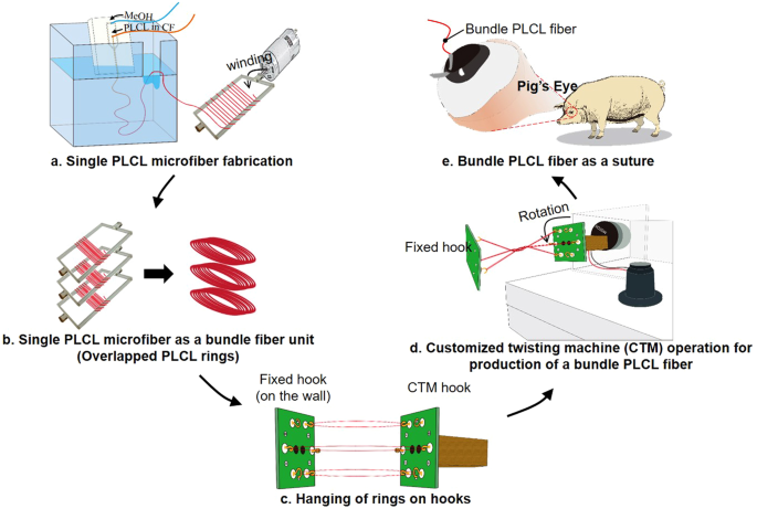
on the anastomosis. As shown in Fig. 1, we first showed that the conventional microfiber spinning chip has an intrinsic ability to control the mechanical properties of single microfibers,
and provided a mathematical explanation for this ability (Fig. 1a). A customized twisting machine (CTM) was built to form bundle fibers based on single microfibers. The measurements of the
mechanical properties of the bundle fiber were assessed according to the number of single fibers contained in the fiber (Fig. 1b–d). In addition, the effects of mixing a biomolecule with a
single microfiber, or coating the biomolecule on the bundle fiber, on the mechanical properties of the bundle fiber were determined. Finally, we stitched up an incision made in a porcine
cornea using a poly(l-lactic-co-ε-caprolactone) (PLCL) bundle fiber to check the effects of the mechanical properties of the suture on the tissue (Fig. 1e). These experiments were carried
out with the pig eye itself, not with eyes of pigs alive. Optical coherence tomography (OCT) images of the operated-upon eyes were acquired to observe the effect of matching the mechanical
properties of the biomaterials with those of the target tissue, and we found that good anastomotic strength control by suggested method would lead us to better post-operative results. This
fabrication method has broadened the applications of microfluidic spinning microfibers, especially to their use as surgical sutures. MATERIALS AND METHODS MECHANICAL PROPERTY CONTROL OF
SINGLE PLCL MICROFIBER FABRICATION OF SINGLE PLCL MICROFIBER USING MICROFLUIDIC CHIP In order to demonstrate the ability of a microfiber-spinning chip imparting various mechanical properties
onto the microfibers, we first fabricated the microfiber using microfluidic spinning chip as done before22,23,24,33,34,35,36. We introduced a PLCL solution (in chloroform) as a sample flow
and methanol as a sheath flow into a core inlet and sheath inlet, respectively, to form a laminar flow. Then, solvents of each solution (chloroform for the PLCL solution, and methanol)
diffused into each other, which caused the precipitation of PLCL since PLCL is insoluble in methanol. As shown in Fig. 1a, we set the direction of the fiber extrusion to be parallel to the
direction of gravity, by hanging the chip in the bath, in order to prevent the interference of fiber fabrication due to the sinking of chloroform within the channel. To minimize the change
in fabrication conditions caused by the hydrostatic force of methanol, we positioned the drainage of the bath to be 1 mm higher than the position of the end of the outlet channel. We only
used microfibers extruded from the outlet in the shape of a straight line and that appeared white when observed by the naked eye, together denoted as a ‘feasible condition’, for subsequent
experiments. In the non-feasible conditions, microfibers extruded from the outlet were transparent. Here, the conditions tested were the molar ratio of PLLA to that of PLCL (5:5 and 7:3),
and the core flow rate when the sheath flow rate was 20 mL/h, 30 mL/h, and 40 mL/h. EQUATION EXPLAINING THE MECHANICAL PROPERTY CONTROL OF SINGLE PLCL MICROFIBER To explain these phenomena,
we suggested a simple equation for the relationship between length density (ρ_l_) of PLCL molecules in the microfiber and the initial Young’s modulus (iYm). iYm was determined from the slope
of the Stress-Strain (SS) curve between 0% and 20% of the strain. The equation is $${\rho }_{l}\propto \frac{{Q}_{PLCL,k}\times {A}_{k}}{{Q}_{MeOH,k}}$$ (1) where k indicates a specific
condition, QPLCL is the core flow rate, QMeOH is the sheath flow rate, and Ak is the cross-sectional area of the microfiber. The derivation of this equation is described as followed: Based
on our hypothesis that the distribution of PLCL molecules in the axial direction of the microfiber affects the iYm of the microfiber, we compared length density with iYm. The derivation of
the equation (1) for the length density of the microfiber resulted from the following steps. * 1. Length density of the microfiber is $${{\rm{\rho }}}_{{\rm{l}}}=\frac{{\rm{M}}}{{\rm{l}}}$$
(2) where l is the length of the microfiber that yields the same mass in each condition, and M is the mass of the microfiber. * 2. In our experimental conditions, the number of PLCL
molecules is proportional to mass and the volume of the microfiber, so equation (2) can be modified to be $${{\rm{\rho }}}_{{\rm{l}}}=\frac{{\rm{M}}}{{\rm{l}}}\propto
\frac{{{\rm{V}}}_{{\rm{constant}}}}{{\rm{l}}}=\frac{{{\rm{Q}}}_{{\rm{PLCL}},k}\times {{\rm{t}}}_{{\rm{k}}}}{{\rm{l}}}$$ (3) where _k_ denotes a specific experimental condition, and tk is the
spinning time for making a fiber of the same mass (Vconstant) in condition _k_. * 3. l can be expressed as a function of tk and the speed at which the fiber is extruded from the outlet in
condition k (vthroughput, k), which could be expressed as $${\rm{l}}={{\rm{t}}}_{{\rm{k}}}\times {{\rm{v}}}_{{\rm{throughput}},{\rm{k}}}$$ (4) * 4. In the case of microfluidic fiber
spinning, since the sample flow rate is much less than the sheath flow rate, equation (4) can be modified to be $${\rm{l}}={{\rm{t}}}_{{\rm{k}}}\times
\frac{{{\rm{Q}}}_{{\rm{MeOH}},{\rm{k}}}}{{{\rm{A}}}_{{\rm{k}}}},\,({{\rm{v}}}_{{\rm{throughput}},{\rm{k}}}\approx \frac{{{\rm{Q}}}_{{\rm{MeOH}},{\rm{k}}}}{{{\rm{A}}}_{{\rm{k}}}})$$ (5) where
Ak is the cross-sectional area of the microfiber in condition k. * 5. Substituting equation (5) into equation (3) yields $${\rho }_{{\rm{l}}}\propto
\frac{{{\rm{Q}}}_{{\rm{P}}{\rm{L}}{\rm{C}}{\rm{L}},{\rm{k}}}\times {{\rm{t}}}_{{\rm{k}}}}{{{\rm{t}}}_{{\rm{k}}}\times
\frac{{{\rm{Q}}}_{{\rm{M}}{\rm{e}}{\rm{O}}{\rm{H}},{\rm{k}}}}{{{\rm{A}}}_{{\rm{k}}}}}=\frac{{{\rm{Q}}}_{{\rm{P}}{\rm{L}}{\rm{C}}{\rm{L}},{\rm{k}}}\times
{{\rm{A}}}_{{\rm{k}}}}{{{\rm{Q}}}_{{\rm{M}}{\rm{e}}{\rm{O}}{\rm{H}},{\rm{k}}}}$$ (6) That is, the length density of a PLCL molecule of a microfluidically spun microfiber is proportional to
the ratio of sample flow rate to sheath flow rate and is proportional to Ak. Experimentally determined iYm values and length densities calculated according to above equation were plotted for
microfibers made using core flow rates of 6, 7, 8, 9, and 10 μL/min with sheath flow rates of 20 mL/h, 30 mL/h, and 40 mL/h for the (5:5)PLCL microfibers. (We investigated that the feasible
condition of core flow rate of 6, 7, 8, 9, and 10 μL/min for sheath flow rate of 20 mL/h was also a feasible condition for sheath flow rate of 30 mL/h and 40 mL/h). MECHANICAL PROPERTY
CONTROL OF BUNDLE PLCL FIBER FABRICATION OF BUNDLE PLCL MICROFIBER USING THE CTM Bundle fibers were constructed from single microfibers whose mechanical properties differed from one another
using the CTM. Immediately after single microfibers were extruded from the microfiber-spinning chip, we collected them around an acryl spool (20 mm width) to form a ring of overlapping PLCL
microfibers (Fig. 1b). The length of the outlet channel and flow condition were set appropriately (i.e., 9 mm) for imperfect precipitation of chloroform to occur within the chip, and the
remaining chloroform on the surface of the microfiber was simply collected and allowed to bond together. Then, rings of overlapping PLCL microfibers were loaded onto a CTM. The CTM was
designed to have three parts: a controller used to determine the twisting direction and speed, hooks used to load various numbers of microfibers, and a motor to drive the twisting. The
bundle fibers were made by loading a specified number of single microfiber strands; in this regard, we also made a fixed hook on the wall, which was used to maintain the distance from the
CTM hook to fixed hook in order to maintain the twisting condition. One side of each overlapped ring was hung on a hook of the CTM, and another side of the ring was hung on a fixed hook, far
enough away (20 mm) from the CTM hook to flatten the ring (Fig. 1c). The twisting rate, time and direction were set on the controller as 60 rpm, two minutes, and a clockwise, respectively.
Then, the operation of the motor formed the bundle PLCL fiber (Fig. 1d). Since it was the ring of overlapping microfibers that was loaded, the number of microfiber strands contained in the
bundle fiber was double the number of times the single microfiber was wound around the spool. Therefore, since we wound a single microfiber around the acryl spool either 4, 8, or 12 times,
the twisted bundle fibers wound up having had eight (4 × 2), sixteen (8 × 2), or twenty-four (12 × 2) microfiber-strands (‘twisted group’). We also loaded either two or three twisted bundle
fibers onto the CTM, so the final bundle fibers in the former case contained either sixteen (2 × 4 × 2), thirty-two (2 × 8 × 2), or forty-eight (2 × 12 × 2) single microfiber strands (‘wound
group’). COATING THE BUNDLE FIBER WITH AN ALGINATE SOLUTION AND MIXING HDECM WITH PLCL PLCL fibers were coated with alginate by passing the bundle fiber soaked in a 2% CaCl2 solution (in
methanol) through a drop of a 2% alginate solution three times (Fig. S2). The method used to mix PLCL with hdECM was developed by Tae Hee Kim of Korea University (data not published yet).
Details of this method are not shown here but will be shown in another paper. However, briefly, porcine heart (obtained from Myung-in bio, Republic of Korea) and 100% acetic acid was
prepared for mixing. We mixed the hdECM solution with the PLCL solution in chloroform to obtain an hdECM-to-PLCL mass ratio of 1:9 or 2:8. It took about a day using a stirring bar to achieve
mixed state before being used. MORPHOLOGY OBSERVATION USING SEM SEM images of each fiber fabricated under feasible and non-feasible conditions were acquired to observe their morphologies
and measure their diameters. All fibers were placed in a methanol bath overnight after the fabrication process and, to remove all evaporative elements, were placed in a vacuum for at least
30 minutes before being placed in the SEM apparatus. CHARACTERIZATION OF THE MECHANICAL PROPERTIES OF A SINGLE PLCL MICROFIBER AND BUNDLE FIBER We quantified the mechanical properties of
single microfibers and bundle fibers by analyzing SS curves. To obtain SS curves, we loaded fibers onto an Instron 5966 machine. But first, in order to load the fibers, we made a nick on a
wooden rod and put the sample fiber in the wooden rod. Then, the wooden rod with fibers was loaded onto Instron tensile zig, which is the part to fix the sample in the tensile test, to avoid
having the fibers slip and hence avoid the formation of distortions in the SS curve (Fig. S3). Single microfibers and bundle fibers loaded onto the Instron machine were set as a geometry of
circular shape and irregular shape, respectively, and pulled at a rate of 10 mm/min until they broke. Another pulling rate of 5 mm/min was also applied to twisted groups to see the effect
on the mechanical response. Since it was relatively difficult to say the bundle fibers are perfect circular shape, we set them as irregular shape and the cross-sectional area was determined
by first measuring the diameters of its single component microfibers, then calculating the individual cross-sectional areas of the individual microfibers from these diameters, and finally
adding up the values of these individual cross-sectional areas. All experiments including fabrication and mechanical properties measurement were conducted under constant temperature (20 °C)
and relative humidity (40%). Then, the SS curve for each condition was obtained. The elongation at break, ultimate tensile strength (UTSH) were measured, and ultimate tensile stress (UTSS)
and iYm were calculated. The UTSS was determined from the UTSH divided by cross-sectional area of the fiber while the iYm was determined from the slope of the SS curve between 0% and 20% of
the strain. Each condition was tested with six independent samples. Analyzing SS curve was performed using Origin 8.0 program. DSC ANALYSIS Thermal properties of both pure PLCL microfibers
and PLCL microfibers containing hdECM were measured to verify the role of hdECM in improving the mechanical properties of PLCL microfibers. Measurements were taken using a Q10 DSC instrument
(TA Instruments, New Castle, DE, USA) with nitrogen as a purge gas. Microfiber samples each with a mass of about 5–10 mg were prepared. The results were obtained from conditions including a
heating rate of 20 °C/min and temperature range of −20 °C to 150 °C. _EX VIVO_ SURGERY In order to verify the advantages of being able to determine the mechanical properties of PLCL fibers,
_ex vivo_ ophthalmology surgery experiments were performed on pig eyes itself, not with eyes of pigs alive. Excised pig eyes were obtained from a local slaughterhouse. They were washed
clearly and transported in phosphate buffer saline at a temperature of 5 °C. Based on the conditions of the system developed for controlling the mechanical properties of biomaterials, we
performed cornea surgery using a fabricated bundle fiber whose mechanical properties relatively well matched the mechanical properties of the porcine cornea (Fig. 1e). The Young’s modulus
and UTSS of the porcine cornea were reported to be 0.1449 MPa9 and 3.70 MPa10, respectively. We used 8 times wound group bundle fiber that included hdECM in its microfibers and that showed
an initial Young’s modulus of 0.125 MPa and UTSS of 50 MPa. While by no means could this fiber, according to these values, be considered a perfect match for the porcine cornea, they were
more mechanically favorable for the cornea than is a nylon suture37,38,39. We then connected the bundle PLCL fiber to the surgical needle, detached from the surgical suture product (Ailee
Co., Ltd, lot number 0300177), to use it as a surgical suture. An incision was made on the cornea and _ex vivo_ surgery performed with the bundle PLCL suture and a nylon 10–0 suture
(Ethicon, ethilon10–0) as a control. We injected saline through the incision site to verify that no leakage happened after surgery. One hour after surgery, we used CirrusTM HD-OCT (ZEUS) of
the cornea to observe the effect of the suture on the anastomosis and, in turn, the morphology of the cornea. RESULTS Feasible conditions were found that core flow rates from 5 μL/min to 10
μL/min were for the 5% (5:5)PLCL solution when sheath flow rates were 20 mL/h and 30 mL/h, while 6 μL/min to 10 μL/min for 5% (5:5) PLCL solution of sheath flow rates of 40 mL/h. The
diameters of fibers fabricated under each feasible conditions were shown in Fig. 2b. Core flow rates from 6 μL/min to 8 μL/min were a feasible condition for the 5% (7:3)PLCL solution. The
changes in an elongation at break, UTSH, UTSS, iYm of a single PLCL microfiber were shown in the SS curves. (Fig. 2c and d) The above mechanical properties associated with changing the molar
ratio were derived from, respectively, the data in Fig. 2c and by comparing the data of Table 2 to the data of Table 3. Compared with 5% (5:5)PLCL microfiber, the 5% (7:3)PLCL microfiber
showed overall higher UTSH, UTSS, and iYm values within the range of feasible conditions. On the other hand, the (5:5)PLCL microfiber showed a super-elastic increase of about 1200% for the
first Instron loading length, but the (7:3)PLCL microfiber showed only an approximately 400% increase. Second, the changes in the SS curve and the above mechanical properties associated with
changing the core flow rate (and keeping the sheath flow rate fixed at 20 mL/h) were derived from, respectively, the data in Fig. 2d and from the data of Table 2 and Table 3. Within the
feasible conditions using the 5% (5:5)PLCL solution, the single microfiber diameter increased and the UTSH did not show any significant difference as the core flow rate was increased, while
UTSS and iYm showed minimum values at 9 μL/min. Within the feasible conditions using the 5% (7:3)PLCL solution, as the core flow rate was increased, again the diameter increased and UTSH did
not show a significant difference, while UTSS and iYm decreased. Also, when comparing the plot of experimentally determined iYm values (Fig. 3a) and length densities calculated according to
suggested equation (Fig. 3b), similar trends were observed. Bundle PLCL fibers of a twisted group and a wound group were well constructed using a CTM to see the effect of the number of
single microfiber strands included in the bundle fiber. (Fig. 4a and b) Since pulling rates are important factors for mechanical response determination at this experiment, two conditions (10
mm/min and 5 mm/min) were applied for twisted groups. Furthermore, we also tested other ways to control the overall mechanical properties of the bundle fibers, including by coating them
with alginate (Fig. 4c-1,c-2) or using microfibers formed after first mixing PLCL with porcine heart decellularized extracellular matrix (hdECM). (Fig. 4d) For the number of the single
microfibers included in the bundle fiber, Table 4 shows the mechanical properties of the twisted and wound groups according to the number of single microfiber strands included in a bundle
fiber. Most notably, the number of single microfiber strands included in the bundle fiber was found to have a negligible effect on the elongation at break, UTSS, and iYm. In contrast, UTSH
was found to increase linearly with the number of single microfiber strands (R2 = 0.96). The effect of pulling rates on mechanical responses of bundle fiber was shown in Figure S4 that,
first, the shape of SS curves differs that, before last shoot to the UTSS, they have quasi-plateau region whose values of stress are much smaller than those of 10 mm/min. Second, iYm values
for group of 4 × 2 and 8 × 2 are bigger than those of 10 mm/min. As shown in Fig. 4e–h, the alginate-coated bundle fibers (red bars) showed slightly lower elongation at break and greater iYM
values than did the pure bundle fibers (black bars), and no significant differences in UTSH and UTSS were measured between these fibers. In the case of the bundle fibers resulting from
mixing hdECM with, the characterization was performed for fibers with a mass ratio of hdECM to (5:5)PLCL of 1:9 (blue bars in Fig. 4e–h) or 2:8 (green bars in Fig. 4e–h). The elongation at
break for the 1:9 case was less than that for the pure bundle fiber; while the UTSH, UTSS, and iYM values for the 1:9 case were greater. However, the overall mechanical properties were worse
for the fiber resulting from mixing hdECM and PLCL at a mass ratio of 2:8. This observation was attributed to the phase separation of the hdECM solution from the PLCL solution.
Inhomogeneous mixing was observed, according to various experiments, in the mixed solution when more than 15% of the mass of the fiber was hdECM (data not shown). This observation implied an
inhomogeneous distribution of PLCL molecules on a single microfiber, which can be explained as being due to a partial defect. Even worse mechanical properties were observed for a microfiber
spun a week after mixing an hdECM solution and PLCL solution (Fig. S5). An incision was made on the cornea (Fig. 5a) and was stitched up using the bundle PLCL suture (Fig. 5b) and a nylon
10–0 suture. No leakage was observed for both cases when injecting saline. One hour after _ex vivo_ surgery, the incision line on the surface of the cornea was verified. (white dotted line
in each of Fig. 5d,e,g and h) As shown in Fig. 5e and h, the cornea sutured with nylon10–0 showed a rough surface. On the other hand, when the bundle PLCL fiber was used as the suture, the
post-operative cornea surface appeared smooth. We observed that the knots of the Nylon10–0 group and the PLCL group did not become untied for 5 days and ended the observation. DISCUSSION For
a single PLCL microfiber, we have confirmed that not only the composition ratio but also the core flow rate change could vary the mechanical properties of microfluidic spinning microfiber.
This difference shown between (5:5)PLCL microfibers and (7:3)PLCL microfiber may have been due to an increase in the amount of rigid L-lactic acid relative to caprolactone, but
crystallization associated with the precipitation of (7:3)PLCL was apparently also an important factor. Also, we observed the plots of experimentally determined iYm and the length density in
the fiber according to the equations we presented have consistent tendency. Since the equation (1) implies the length density of molecules along the axial direction of the microfiber to be
determined by the ratio of the core flow rate to the sheath flow rate, and the area of the microfiber was previously indicated to be determined by the structure of the spinning chip and the
flow rate40, we concluded that a microfluidic spinning chip can inherently control mechanical properties. Especially, our method in which a fiber is produced by precipitation within a chip
has slow rate of fiber generation41, which gave time for a rearrangement of fiber molecules before perfect precipitation within the chip (note the definition of feasible condition), and was
the main factor controlling the mechanical properties of the microfibers. The mechanical properties of a microfiber may thus be designed by simply using conventional spinning microchips as
follows: changing the base materials to induce changes in certain mechanical properties such as elasticity, and changing the spinning flow condition to induce changes in the UTSS and Young’s
modulus without significant changes in elasticity and UTSH. Thus, we concluded that when the conventional microfiber-spinning chip was used, we found the base material to be critical for
determining the overall characteristics of the fibers; thus choosing the appropriate base material should be the first step in designing biomaterials that are intended to meet the need of
the target tissues. Even with the same material, fine and independent control of the mechanical properties was shown to be possible using the microfluidic spinning chip. For a bundle PLCL
fiber, we were able to use a CTM to make a bundle fiber with different UTSH values, by changing the number of strands, while keeping the UTSS and iYm value relatively constant. Given that,
of the twisted group, the angle of the internal microfiber with respect to the direction of the bundle fiber was found to have no significant relationship with measured mechanical
properties, (Figure S7 and Supporting Information) the number of strands, rather than the angle of the microfiber within the bundle fiber, played a main role in controlling mechanical
properties of the fiber in our system. The effect of pulling rate on the mechanical response of the fiber shows the properties of PLCL. Since PLCL is very elastic, it can be lengthened to
about 800–900% of the initial length. In this regard, the different tendency of the SS curve seems to depend on the relation between the pulling rate, that is, the time that the force is
given and the time required for the maximum deformation of the PLCL by the specific stress. Two remarkable characteristics at Figure S4, the quasi-plateau and different iYm for twisted
groups of 4 × 2 and 8 × 2, may be due to similar or shorter time at which the force is applied to time at which the maximum deformation of the PLCL by the stress was done, unlike the case of
10 mm/min. We were also able to control mechanical properties of the fibers by coating them with biomolecules or blending biomolecules into them. Coating bundle PLCL fiber with alginate
shows greater iYm values than did the pure bundle fibers with no other significant difference. This result may have been due to the difference in elongation at break of alginate and PLCL
being so large that the values measured at the end of the elongation were not reflected in the alginate properties but the values for alginate were reflected in the iYM values. Also, less
elongation at break, greater UTSH, UTSS, and iYm were shown for the 1:9 mixing case, while the overall mechanical properties were worse for the 2:8 mixing case. For 1:9 mixing case, These
results resembled the differences between (5:5)PLCL and (7:3)PLCL. That is, mixing the hdECM with the PLCL solution changed the mechanical properties of the single microfiber itself, and
this change caused a change in the mechanical properties of the bundle fiber. The change in the properties of the single microfiber might have been due to the filler effect, i.e., that hdECM
acted as filler to improve the mechanical properties of the microfiber. Actually, many papers including our unpublished ones (in press) prove this42,43. While we originally might have
expected hdECM to help harden the microfiber by either being a crystal nucleus or filler, we actually found that hdECM did not act as crystal nucleus and only acted as a filler to enhance
the strength of the microfiber. As shown in Figure S6, significant changes were observed neither in the melting point nor in the glass transition temperature upon including hdECM, according
to differential scanning calorimetry (DSC) results. For 2:8 mixing case, phase separation of the hdECM solution from the PLCL solution attributed to the results. Inhomogeneous mixing was
observed, according to various experiments, in the mixed solution when more than 15% of the mass of the fiber was hdECM (data not shown). This observation implied an inhomogeneous
distribution of PLCL molecules on a single microfiber, which can be explained as being due to a partial defect. The observation of OCT images of the porcine cornea surface after surgery
suggested that bundle PLCL fiber, applied as a suture, did not induce unmatched anastomotic strength and not induce the distortion of the surface structure while nylon suture could. This
observation indicated that there was less scar formation, less of a delay in the wound healing process, or a lower concern that astigmatism developed when bundle PLCL fiber was used as a
suture than when the nylon was used. These results implied that designing biomaterials to have mechanical strengths matching the mechanical strength of the target tissue is important when
using biomaterials to maintain or restore tissue structure or function. Noting that the nylon10–0 surgical suture is one of the most commonly used sutures in ophthalmology surgery, the
bundle PLCL fiber can be utilized as a suture and developed into a commodity. One hurdle of this method was that it was difficult to connect a bundle fiber to a fine surgical needle in the
laboratory, and we had to inevitably attach the bundle fiber to a thick needle, which could increase needle-induced damage to tissue. However, this issue can be easily solved with a help of
suture fabrication company in the near future. CONCLUSIONS In summary, we developed a system which consists of a microfluidic spinning chip and a CTM, and where quite easily, we could
independently control different mechanical properties of fibers. First, using a spinning chip, we were able to change the UTSS and iYm values while keeping the UTSH relatively constant. This
ability was presumably due to the molecular arrangement of the base material in the fiber depending on the flow environment. Secondly, the relationship between the unit microfiber and
bundle fiber in this bottom-up fabrication system can be summarized as follows: we were able to change the elongation at break, iYm, and UTSS of the bundle fiber by changing the properties
of the unit microfiber itself, while we changed the UTSH of the bundle fiber mainly by changing the number of single microfibers in the bundle fiber. In other words, we have constructed
bundle fibers whose mechanical properties can be tuned independently. We also conducted experiments in an applied case, and have shown once again the importance the of the mechanical design
of the biomaterial for either case of being applied or being implanted. Overall, the current work has suggested an easy and novel method to control the mechanical properties of fiber-form
biomaterials, which increased the range of potential applications of fibers by having developed a way to better control their mechanical properties. CHANGE HISTORY * _ 31 AUGUST 2018 A
correction to this article has been published and is linked from the HTML and PDF versions of this paper. The error has been fixed in the paper. _ REFERENCES * Gimbel, H. V., Raanan, M. G.
& DeLuca, M. Effect of suture material on postoperative astigmatism. _J Cataract Refract Surg_ 18, 42–50 (1992). Article PubMed CAS Google Scholar * Saxena, S. _et al_. Development
of a new polypropylene-based suture: plasma grafting, surface treatment, characterization, and biocompatibility studies. _Macromol Biosci_ 11, 373–382, https://doi.org/10.1002/mabi.201000298
(2011). Article PubMed CAS Google Scholar * Xu, G.-K., Li, B., Feng, X.-Q. & Gao, H. A tensegrity model of cell reorientation on cyclically stretched substrates. _Biophysical
journal_ 111, 1478–1486 (2016). Article ADS PubMed PubMed Central CAS Google Scholar * Poole, T. R. & Ficker, L. A. Astigmatic keratotomy for post-keratoplasty astigmatism. _J
Cataract Refract Surg_ 32, 1175–1179, https://doi.org/10.1016/j.jcrs.2006.01.103 (2006). Article PubMed Google Scholar * Ambekar, R., Toussaint, K. C. Jr. & Wagoner Johnson, A. The
effect of keratoconus on the structural, mechanical, and optical properties of the cornea. _J Mech Behav Biomed Mater_ 4, 223–236, https://doi.org/10.1016/j.jmbbm.2010.09.014 (2011). Article
PubMed Google Scholar * Cox, T. R. & Erler, J. T. Remodeling and homeostasis of the extracellular matrix: implications for fibrotic diseases and cancer. _Dis Model Mech_ 4, 165–178,
https://doi.org/10.1242/dmm.004077 (2011). Article PubMed PubMed Central CAS Google Scholar * Aguiari, P., Fiorese, M., Iop, L., Gerosa, G. & Bagno, A. Mechanical testing of
pericardium for manufacturing prosthetic heart valves. _Interact Cardiovasc Thorac Surg_ 22, 72–84, https://doi.org/10.1093/icvts/ivv282 (2016). Article PubMed Google Scholar * Khanafer,
K. _et al_. Determination of the elastic modulus of ascending thoracic aortic aneurysm at different ranges of pressure using uniaxial tensile testing. _J Thorac Cardiovasc Surg_ 142,
682–686, https://doi.org/10.1016/j.jtcvs.2010.09.068 (2011). Article PubMed Google Scholar * Holzapfel, G. A. Biomechanics of soft tissue. _The handbook of materials behavior models_ 3,
1049–1063 (2001). Google Scholar * Barthelat, F. Biomimetics for next generation materials. _Philos Trans A Math Phys Eng Sci_ 365, 2907–2919, https://doi.org/10.1098/rsta.2007.0006 (2007).
Article ADS MathSciNet PubMed CAS Google Scholar * Johnson, G. A. _et al_. Tensile and viscoelastic properties of human patellar tendon. _J Orthop Res_ 12, 796–803,
https://doi.org/10.1002/jor.1100120607 (1994). Article PubMed CAS Google Scholar * Lujan, T. J. _Multiscale Relationships of Ligament Mechanics_ (ProQuest, 2007). * Jue, B. &
Maurice, D. M. The mechanical properties of the rabbit and human cornea. _J Biomech_ 19, 847–853 (1986). Article PubMed CAS Google Scholar * Soza, G. _et al_. Determination of the
elasticity parameters of brain tissue with combined simulation and registration. _Int J Med Robot_ 1, 87–95, https://doi.org/10.1002/rcs.32 (2005). Article PubMed CAS Google Scholar *
Mow, V. C. & Huiskes, R. _Basic orthopaedic biomechanics & mechano-biology_ (Lippincott Williams & Wilkins, 2005). * Pal, S. In _Design of Artificial Human Joints & Organs_
23-40 (Springer, 2014). * Buttafoco, L. _et al_. Electrospinning of collagen and elastin for tissue engineering applications. _Biomaterials_ 27, 724–734,
https://doi.org/10.1016/j.biomaterials.2005.06.024 (2006). Article PubMed CAS Google Scholar * Agrawal, P. & Pramanik, K. Chitosan-poly (vinyl alcohol) nanofibers by free surface
electrospinning for tissue engineering applications. _Tissue Eng Regen Med_ 13, 485–497 (2016). Article CAS Google Scholar * Ozbolat, I. T. & Hospodiuk, M. Current advances and future
perspectives in extrusion-based bioprinting. _Biomaterials_ 76, 321–343, https://doi.org/10.1016/j.biomaterials.2015.10.076 (2016). Article PubMed CAS Google Scholar * Kim, J. E., Kim,
S. H. & Jung, Y. Current status of three-dimensional printing inks for soft tissue regeneration. _Tissue Eng Regen Med_ 13, 636–646 (2016). Article CAS Google Scholar * Cheng, J.,
Jun, Y., Qin, J. & Lee, S. H. Electrospinning versus microfluidic spinning of functional fibers for biomedical applications. _Biomaterials_ 114, 121–143,
https://doi.org/10.1016/j.biomaterials.2016.10.040 (2017). Article PubMed CAS Google Scholar * Kang, E. _et al_. Digitally tunable physicochemical coding of material composition and
topography in continuous microfibres. _Nat Mater_ 10, 877–883, https://doi.org/10.1038/nmat3108 (2011). Article ADS PubMed CAS Google Scholar * Jun, Y. _et al_. Microfluidics-generated
pancreatic islet microfibers for enhanced immunoprotection. _Biomaterials_ 34, 8122–8130, https://doi.org/10.1016/j.biomaterials.2013.07.079 (2013). Article PubMed CAS Google Scholar *
Park, D. Y. _et al_. One-stop microfiber spinning and fabrication of a fibrous cell-encapsulated scaffold on a single microfluidic platform. _Biofabrication_ 6, 024108 (2014). Article ADS
PubMed CAS Google Scholar * Onoe, H. & Takeuchi, S. Cell-laden microfibers for bottom-up tissue engineering. _Drug Discov Today_ 20, 236–246,
https://doi.org/10.1016/j.drudis.2014.10.018 (2015). Article PubMed CAS Google Scholar * Ahn, S., Mun, C. & Lee, S. H. Microfluidic spinning of fibrous alginate carrier having highly
enhanced drug loading capability and delayed release profile. _RSC Advances_ 5, 15172–15181 (2015). Article CAS Google Scholar * Kitagawa, Y., Naganuma, Y., Yajima, Y., Yamada, M. &
Seki, M. Patterned hydrogel microfibers prepared using multilayered microfluidic devices for guiding network formation of neural cells. _Biofabrication_ 6, 035011 (2014). Article ADS
PubMed CAS Google Scholar * Kang, E. _et al_. Microfluidic spinning of flat alginate fibers with grooves for cell-aligning scaffolds. _Adv Mater_ 24, 4271–4277,
https://doi.org/10.1002/adma.201201232 (2012). Article PubMed CAS Google Scholar * Jeong, G. S. & Lee, S.-H. Microfluidic spinning of grooved microfiber for guided neuronal cell
culture using surface tension mediated grooved round channel. _Tissue Eng Regen Med_ 11, 291–296 (2014). Article Google Scholar * Tamayol, A. _et al_. Flexible pH-Sensing Hydrogel Fibers
for Epidermal Applications. _Adv Healthc Mater_ 5, 711–719, https://doi.org/10.1002/adhm.201500553 (2016). Article PubMed PubMed Central CAS Google Scholar * Shi, X. _et al_.
Microfluidic Spinning of Cell‐Responsive Grooved Microfibers. _Advanced Functional Materials_ 25, 2250–2259 (2015). Article CAS Google Scholar * Mun, C. H., Hwang, J.-Y. & Lee, S.-H.
Microfluidic spinning of the fibrous alginate scaffolds for modulation of the degradation profile. _Tissue Eng Regen Med_ 13, 140–148 (2016). Article CAS Google Scholar * Cheng, J. _et
al_. Biomimetic spinning of silk fibers and _in situ_ cell encapsulation. _Lab Chip_ 16, 2654–2661, https://doi.org/10.1039/c6lc00488a (2016). Article PubMed CAS Google Scholar * Park,
D. _et al_. Simultaneous microfluidic spinning of multiple strands of submicron fiber for the production of free-standing porous membranes for biological application. _Biofabrication_ 9,
025026, https://doi.org/10.1088/1758-5090/aa7307 (2017). Article ADS PubMed Google Scholar * Cho, S., Shim, T. S. & Yang, S. M. High-throughput optofluidic platforms for mosaicked
microfibers toward multiplex analysis of biomolecules. _Lab Chip_ 12, 3676–3679, https://doi.org/10.1039/c2lc40439g (2012). Article PubMed CAS Google Scholar * Chae, S. K., Kang, E.,
Khademhosseini, A. & Lee, S. H. Micro/Nanometer-scale fiber with highly ordered structures by mimicking the spinning process of silkworm. _Adv Mater_ 25, 3071–3078,
https://doi.org/10.1002/adma.201300837 (2013). Article PubMed CAS Google Scholar * Chu, C. C. Mechanical properties of suture materials: an important characterization. _Ann Surg_ 193,
365–371 (1981). Article PubMed PubMed Central CAS Google Scholar * Rennie, L., Fleming, W., Clark, D., Ellerton, C. & Bosanquet, R. Some mechanical properties of 10/0 monofilament
nylon sutures. _Eye (Lond)_ 8(Pt 3), 343–345, https://doi.org/10.1038/eye.1994.71 (1994). Article Google Scholar * Callahan, T. L., Lear, W., Kruzic, J. J. & Maughan, C. B. Mechanical
properties of commercially available nylon sutures in the United States. _J Biomed Mater Res B Appl Biomater_ 105, 815–819, https://doi.org/10.1002/jbm.b.33600 (2017). Article PubMed CAS
Google Scholar * Zarrin, F. & Dovichi, N. J. Sub-picoliter detection with the sheath flow cuvette. _Analytical chemistry_ 57, 2690–2692 (1985). Article CAS Google Scholar * Jun, Y.,
Kang, E., Chae, S. & Lee, S.-H. Microfluidic spinning of micro-and nano-scale fibers for tissue engineering. _Lab on a Chip_ 14, 2145–2160 (2014). Article PubMed CAS Google Scholar *
Zhang, Y., Ouyang, H., Lim, C. T., Ramakrishna, S. & Huang, Z. M. Electrospinning of gelatin fibers and gelatin/PCL composite fibrous scaffolds. _Journal of Biomedical Materials
Research Part B: Applied Biomaterials_ 72, 156–165 (2005). Article CAS Google Scholar * Lee, J. _et al_. The effect of gelatin incorporation into electrospun poly
(l-lactide-co-ɛ-caprolactone) fibers on mechanical properties and cytocompatibility. _Biomaterials_ 29, 1872–1879 (2008). Article PubMed CAS Google Scholar Download references
ACKNOWLEDGEMENTS This work was supported by the KU-KIST Graduate School of Converging Science and Technology Program, and by Global Ph.D. Fellowship Program of National Research Foundation,
Republic of Korea [2015H1A2A1033269]. Dr. Cho Hay Mun first suggested the core idea of this experiment. Geon Hui Lee and Seong-Ho Go of Korea University gave us a lot of help in constructing
the CTM. Porcine hdECM and the idea of mixing hdECM with PLCL solution were suggested by Tae Hee Kim of Korea University. We gratefully acknowledge the late Professor Sang-Hoon Lee for
organizing the experiments of all the sessions. AUTHOR INFORMATION Author notes * Sang-Hoon Lee is deceased. AUTHORS AND AFFILIATIONS * KU-KIST Graduate School of Converging Science and
Technology, Korea University, 145 Anam-ro, Seongbuk-gu, Seoul, 02841, Republic of Korea DoYeun Park, Soo Hyun Kim & Sang-Hoon Lee * Department of Bio and Brain Engineering, KAIST,
Daejeon, 34141, Republic of Korea In Sung Yong * Department of Ophthalmology, College of Medicine, Dankook University, 119 Danaeo-ro, Dongnam-gu, Cheonan-si, Chungcheongnam-do, 31116,
Republic of Korea Kyong Jin Cho * MOE Key Laboratory of Spectrochemical Analysis & Instrumentation, Collaborative Innovation Center of Chemistry for Energy Materials, Key Laboratory for
Chemical Biology of Fujian Province, State Key Laboratory of Physical Chemistry of Solid Surfaces, College of Chemistry and Chemical Engineering, Xiamen University, Xiamen, 361005, China Jie
Cheng * Biomaterials Research Center, Korea Institute of Science and Technology, 5, Hwarang-ro 14-gil, Seongbuk-gu, Seoul, 02792, Republic of Korea Youngmee Jung & Soo Hyun Kim * School
of Biomedical Engineering, College of Health Science, Korea University, 145, Anam-ro, Seongbuk-gu, Seoul, 02841, Republic of Korea Sang-Hoon Lee Authors * DoYeun Park View author
publications You can also search for this author inPubMed Google Scholar * In Sung Yong View author publications You can also search for this author inPubMed Google Scholar * Kyong Jin Cho
View author publications You can also search for this author inPubMed Google Scholar * Jie Cheng View author publications You can also search for this author inPubMed Google Scholar *
Youngmee Jung View author publications You can also search for this author inPubMed Google Scholar * Soo Hyun Kim View author publications You can also search for this author inPubMed Google
Scholar * Sang-Hoon Lee View author publications You can also search for this author inPubMed Google Scholar CONTRIBUTIONS D. Park performed main fiber fabrication experiment, created
length density equation, analyzed the data, prepared all figures included in this paper, and wrote main manuscript text; I.S. Yong performed main fiber fabrication experiment; K.J. Cho
performed _ex vivo_ experiment and took OCT images to check the structure of porcine eye; J. Cheng helped fabrication optimization and advised on creating length density equation; Y. Jung
provided PLCL and advised on analyzing the data; S.H. Kim provided PLCL, advised on analyzing the data, edited manuscript, and final approval of manuscript; S.-H. Lee designed and organized
the experiments of all the sessions. CORRESPONDING AUTHOR Correspondence to Soo Hyun Kim. ETHICS DECLARATIONS COMPETING INTERESTS The authors declare that they have no competing interests.
ADDITIONAL INFORMATION PUBLISHER'S NOTE: Springer Nature remains neutral with regard to jurisdictional claims in published maps and institutional affiliations. ELECTRONIC SUPPLEMENTARY
MATERIAL SUPPLEMENTARY INFORMATION RIGHTS AND PERMISSIONS OPEN ACCESS This article is licensed under a Creative Commons Attribution 4.0 International License, which permits use, sharing,
adaptation, distribution and reproduction in any medium or format, as long as you give appropriate credit to the original author(s) and the source, provide a link to the Creative Commons
license, and indicate if changes were made. The images or other third party material in this article are included in the article’s Creative Commons license, unless indicated otherwise in a
credit line to the material. If material is not included in the article’s Creative Commons license and your intended use is not permitted by statutory regulation or exceeds the permitted
use, you will need to obtain permission directly from the copyright holder. To view a copy of this license, visit http://creativecommons.org/licenses/by/4.0/. Reprints and permissions ABOUT
THIS ARTICLE CITE THIS ARTICLE Park, D., Yong, I.S., Cho, K.J. _et al._ The use of microfluidic spinning fiber as an ophthalmology suture showing the good anastomotic strength control. _Sci
Rep_ 7, 16264 (2017). https://doi.org/10.1038/s41598-017-16462-7 Download citation * Received: 25 August 2017 * Accepted: 13 November 2017 * Published: 24 November 2017 * DOI:
https://doi.org/10.1038/s41598-017-16462-7 SHARE THIS ARTICLE Anyone you share the following link with will be able to read this content: Get shareable link Sorry, a shareable link is not
currently available for this article. Copy to clipboard Provided by the Springer Nature SharedIt content-sharing initiative