Play all audios:
ABSTRACT Traditional rectangular tunnel boring machines have low tunneling efficiency, poor soil mixing effects, which has hindered the construction of long-distance and large-section box
jacking projects. To overcome these limitations, a new type of full-face excavation boring machine was developed based on a planetary transmission mechanism. This machine achieves full-face
excavation by utilizing three eccentric cutter heads that revolve around both the central axis of the cutter plate and their individual shafts. The design methodology, feasibility, and
principles of this new mechanism were introduced. Furthermore, a successful construction project of an underground highway passage in Japan was presented as a case study to demonstrate the
design and application of this tunnel boring machine. The case details include the excavation face support mechanism, optimal cutter-head layout, obstacle removal strategies, and methods for
reducing jacking resistance. Monitoring data from the project verified the applicability, reliability, and overall engineering performance of the rectangular shield machine developed using
the planetary mechanism. This research demonstrates that the planetary transmission mechanism-based boring machine offers superior performance in terms of ground settlement and tunneling
speed, potentially providing a comprehensive solution to the challenges in the development of rectangular shield machines for box jacking projects. SIMILAR CONTENT BEING VIEWED BY OTHERS
SAFETY AND ENVIRONMENTAL IMPACT CONTROL OF CROSS PASSAGE CONSTRUCTION IN SOFT SOIL STRATA USING TUNNEL BORING MACHINE METHOD Article Open access 14 September 2023 LARGE RECTANGULAR
CROSS-SECTION TUNNEL UNDERCROSSING URBAN ROAD BY MICRO PIPE JACKING AND JOINT ASSEMBLY STRUCTURE (MPJ & JAS) METHOD IN SOFT SOILS Article Open access 01 March 2024 EFFECTS ON UPPER
MASONRY STRUCTURES CAUSED BY DOUBLE-LINE PARALLEL SHIELD CUTTING GROUP PILE CONSTRUCTION Article Open access 27 September 2024 INTRODUCTION The most commonly used methods for underground
excavation include open face and hand mining methods, drilling and blasting, cantilever tunnel boring machines (TBMs), and full-face TBMs. The hand mining method is primarily suitable for
stable formations but is challenging to apply in urban tunnel projects due to the ground movements and difficult working environment. While drilling and blasting method is mainly used for
rock formations and is also difficult to adapt to urban environments due to vibration and noise issues1. Additionally, compared to cantilever TBMs, full-face TBMs have become the preferred
method for tunnel excavation because of their high advance rate and safety2. However, several challenges remain when using conventional full-face TBMs for non-circular cross-sectional
excavation in urban geological conditions, such as achieving a higher section excavation ratio, improving excavation and spoil removal efficiency, and enhancing the stability of the overall
excavation face. Rectangular cross-sections offer higher space utilization compared to conventional circular shield methods. However, the development of high-efficiency excavation machinery
for rectangular excavation has lagged behind that for circular tunnels. With the emergence of new application scenarios for rectangular underground spaces, such as utility tunnels,
underground parking lots, and underground logistics channels3,4, it is necessary to review the current state of rectangular tunnel boring machines (RTBMs) and develop more efficient
equipment for rectangular excavation. The origin of the rectangular shield machine can be traced back to the Double-O-Tube (DOT) shield5, which was used to construct subway stations by
replacing the parallel twin tunnel or open-cut methods to reduce soil excavation. However, the complex changes in the shield’s sectional profile can cause serious friction resistance during
advancement, leading to the development of the quasi-rectangular TBM to minimize these impacts6. Since then, various RTBMs have been developed to further improve the excavation efficiency
and ratios, including multi-circle types, eccentric multi-shaft types, eccentric double-shaft types, and cylinder types. However, these boring mechanisms still face challenges in achieving
full-face excavation for rectangular cross-sections due to various constraints7,8. In addition, the behavior of the rectangular boring mechanism also affects the ground response after
excavation. For example, in box jacking, if the RTBM’s boring mechanism causes significant disturbance to the surrounding strata during excavation, the arching effect of the overburden may
be compromised, leading to substantial ground surface subsidence9,10. Furthermore, frictional resistance from pipe-soil interaction tends to be more pronounced than in circular conditions
due to ground disturbance and movement, especially under complex geological conditions11. Several countermeasures have been proposed to alleviate these problems in box jacking construction,
focusing on improving the performance of tunnel boring machines (TBMs) and implementing auxiliary measures12. In terms of auxiliary measures, the pipe roof method, for instance, constructs a
retaining wall or stress insulation structure above the main tunnel by combining pre-excavations with micro crosssection.13,14,15. However, controlling the deformation of pre-excavated
sections during main tunnel jacking remains a challenge. Soil improvement is another approach to reducing disturbance from RTBMs, but its effectiveness is highly dependent on grouting
techniques. Additionally, these auxiliary engineering measures can complicate and increase the cost of construction. Therefore, optimizing the performance of RTBMs by improving the boring
mechanism is a more fundamental approach to minimizing the environmental impact during excavation. Developing a new rectangular shield with an advanced boring mechanism to minimize soil
disturbance and enhance boring efficiency is critical for successful box jacking. Key parameters, such as face pressure, tail void size, and soil fluidity in the cabin, controlled by RTBMs,
need to be reevaluated16,17,18. In this context, the key issues and design limitations of conventional RTBMs are reviewed. Furthermore, a full-face excavation cutter-head developed based on
a planetary transmission mechanism is introduced, which demonstrates improved performance in excavation efficiency, mixing efficiency, and adaptability to complex conditions. This design
effectively prevents excessive soil movement at the face and minimizes ground disturbance within the soil’s elastic limits. Finally, a case study is presented to verify the effectiveness of
this new RTBM, particularly regarding its impact on ground stability. KEY TECHNIQUE ISSUES AT THE EXCAVATION FACE Maintaining excavation face stability is paramount for all types of RTBMs
during underground excavation. Studies have shown that the mechanical performance of RTBMs significantly impacts face stability6. Since the 1980s, RTBMs have been designed with various
factors in mind, including soil strength, overburden conditions, soil particle size distribution, and groundwater conditions. However, the engineering performance of these RTBMs often varies
across projects with similar geological conditions, even when using the same boring mechanism and construction scheme. Initially, this variability in outcomes was attributed to
site-specific geological conditions, such as soil mass quality, groundwater conditions, and ground improvements. However, attributing performance issues solely to site geology overlooks
potential shortcomings in equipment design and operation. This oversight hinders progress in addressing technical challenges and limits the effectiveness of RTBMs. Actually, the potential
incompatibility between the excavation face-forming mechanism on the ground side and the fixed functions on the TBM side is the main reason for these issues. In many cases, the expected
performance of the machine is not fully realized, and the stability of the rectangular excavation face is compromised by limitations within the mechanical design of conventional boring
mechanisms19. Therefore, it is necessary to re-evaluate the actual state of the excavation face and the functionalities of RTBMs before proceeding with any redesign. GROUND LOOSENESS The
actual state of the excavation face can be readily assessed in open-shield methods through observations of collapse and ground movement. However, in closed-type box jacking with continuous
excavation, directly observing the excavation face is impossible. In this context, achieving and maintaining stability becomes crucial, regardless of soil properties. Once looseness or
collapse occurs at the excavation face, it becomes difficult for RTBMs to mechanically prevent soil particle fluidization, especially when the ground has limited self-supporting ability.
Therefore, when dealing with soils that have limited self-supporting capabilities, implementing countermeasures to prevent ground looseness at the rectangular excavation face is essential
for ensuring stability16,20. Table 1 presents the fluidization indicators for sandy soil formations used in Japan 21. CONTRADICTIONS OF THE EXCAVATION PROCESS Box jacking is a dynamic
process characterized by fluctuations in pressure at the excavation face. The continuous operation of the boring system within the closed cabin—including soil cutting, spoil handling, and
muck removal—inevitably disrupts the soil mass at the face. Furthermore, during excavation pauses, a mud film forms at the excavation face, giving the illusion of high water-cutting
performance and ground support-ability. However, this film is immediately destroyed by the cutter head when excavation resumes rotation. This cycle of mud film formation and destruction
within the closed cabin underscores the need to effectively utilize both the fixed bulkhead and the flexible cutter heads to achieve a stable soil-retaining effect. Therefore, the design of
RTBMs must address these inherent contradictions in the excavation process. The primary factor affecting soil-retaining effect is the RTBM’s ability to regulate support pressure at the
excavation face22. Theoretically, the support pressure applied by RTBMs must account for the active earth pressure, groundwater pressure, and the preliminary pressure23,] all of which
directly relate to ground deformation during excavation24. If support pressure exceeds the ground’s bearing capacity, the jacking force required to propel the machine forward increases
significantly. This can overload the RTBM’s drive unit and reduce the lifespan of the cutter bits. Additionally, excessive pressure can consolidate the soil within the cabin, decreasing its
fluidity and potentially causing blockages in the spoil removal system. In sandy soil condition, excessive pressure may also lead to the uncontrolled soil ejection (spouting) due to partial
liquefaction. When soil compressibility reaches 2–4%, the soil in front of the excavation face shifts into a passive earth pressure state, causing serious deformation of the surrounding soil
and reducing the RTBM’s flexibility. In practice, RTBM performance should aim to suppress ground deformation and maintain it within the elastic range, allowing the soil to recover its
original state once pressure is released. Therefore, relying solely on Rankine’s passive earth pressure calculations for determining face pressure in box jacking may have significant
drawbacks. Allowing a controlled degree of excavation face deformation can be beneficial for RTBM advancement. SOIL LOSS AROUND THE EXCAVATION FACE The excavating process disturbs the
surrounding soil, leading to its loosening. Existing boring mechanisms mainly use rotating cutter bits to cut the rectangular section. As the soil loosens, the surrounding soil collapses and
enters the excavation face, increasing the soil loss rate20. Thus, conventional cutting systems struggle to prevent soil loss from the surrounding ground. To address this challenge, four
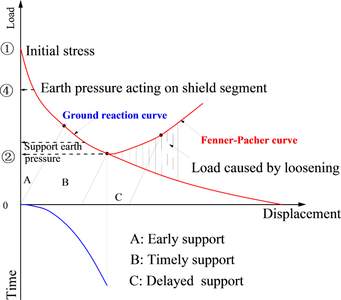
critical areas are proposed for technical improvements that should be prioritized when developing new RTBMs: * 1) Shortening mud film formation time at the excavation face * 2) Passing
through the excavation zone while the ground remains in the elastic state (see the diagram of modified Fenner-Pacher curve in Fig. 1) 25; * 3) Reducing the time for mixing and compressing
spoil by well-designed cutter-head * 4) Identifying a proper cutter bit penetration depth and peripheral speed to promote sediment fluidization PERIPHERAL SPEED OF THE CUTTER-HEAD The
peripheral speed of the cutter head is a critical factor for spoil processing within the excavation chamber of an RTBM. However, the widely used circular cutter head has limitations in its
ability to effectively mix and agitate the spoil as its diameter increases. While a higher peripheral speed on the outer edges of the rotating cutter head can improve cutting rates and
mixing forces in peripheral areas, the rotational velocity decreases significantly towards the center, as shown in Fig. 2. This results in a limited mixing zone in the central region
referred to as the “blind area”. To achieve adequate mixing and stirring within a short excavation cycle, researchers have focused on optimizing the relationship between torque and the
peripheral speed of the outermost portion of the cutter head 26. However, increasing the rotation speed also presents drawbacks. The inertia of the cutters and the excavated soil they carry
increases, leading to greater stress on the surrounding soil. The high-speed rotation of the cutter bits on the outer edges creates a zone of significant disturbance on the far side of the
excavation face, as illustrated in Fig. 3. Therefore, it becomes necessary to explore new solutions to address these shortcomings and enhance the performance of cutter heads for box jacking
applications. BRIEF REVIEW OF RECTANGULAR BORING MECHANISMS CLASSIFICATION OF THE RECTANGULAR BORING MECHANISMS The ultimate purpose of the boring mechanism design for RTBMs is to reduce the
unexcavated area as much as possible, thereby minimizing resistance from the excavation face. To achieve this, various boring mechanisms have been developed to enhance the adaptability and
performance of RTBMs. In light of these efforts, this paper now reviews existing RTBMs with different boring mechanisms (see Fig. 4). These RTBMs could be categorized into 8 specific types:
(1) Drum (paddle) rotating type; (2) Wagging excavation type (including arm retractable type); (3) Eccentric rotating type; (4) Planetary cutter type; (5) Boom cutter type (optional
excavating); (6) Eccentric rotating shaft type; (7) multi-axis rotation type (multi circular cutter-heads arrangement); and (8) Combined excavation type. A common feature of these mechanisms
is the application of high pressure to induce cracks or collapses in unexcavated areas. However, this approach proves ineffective in exceptionally stable ground conditions. Another
prevalent issue is the inconsistency in cutting performance between different cutter heads, which can lead to machine imbalances. Such imbalance may result in excessive torque being applied
to the motors (over-torque) and reduced excavation speed. Therefore, next-generation RTBMs must focus on improving the ability of cutter heads to cope with unexcavated areas. Additionally,
based on existing equipment experience, employing multiple drive devices is crucial for maintaining consistent excavation capability across the entire cross-section, thereby promoting a
balanced machine operation. DEVELOPMENT PERSPECTIVES The preceding discussion on the technical challenges of RTBMs aims to illuminate the path forward for equipment upgrades. However,
manufacturing these machines requires more than just technical considerations; it must also adapt to the evolving construction market. Recognizing this dual necessity, this paper addresses
both technological and market aspects by proposing six key principles for the development of RTBMs: * 1) Relative Superiority: New RTBMs should surpass existing construction methods in terms
of cost-effectiveness, speed, environmental impact, and overall performance. * 2) Compatibility: Ensuring a smooth transition by leveraging existing technologies and designs, this principle
minimizes the need for extensive modifications or entirely new infrastructure. * 3) Simplicity: Focusing on user-friendly designs that operators can easily understand and maintain, this
principle reduces training requirements and the potential for human error. * 4) Experimental feasibility: Highlighting the importance of facilitating empirical testing during development,
this principle supports rapid evaluation and improvement of new designs through clear and straightforward testing methods. * 5) Ease for observation: Emphasizing the value of clear visual
monitoring during operation, this principle enables quick adjustments and troubleshooting by allowing operators to readily observe machine performance. * 6) Market alignment: Underscoring
the importance of aligning RTBM development with current market demands, this principle ensures that new machines address the specific needs identified by construction professionals.: This
principle underscores the importance of aligning RTBM development with current market demands and addressing specific needs identified by construction professionals. Overall, these six
principles offer a comprehensive framework for developing next-generation RTBMs that are not only technically advanced but also user-friendly and commercially viable. NEW RTBM BASED ON
PLANETARY TRANSMISSION MECHANISM Building on the investigation of existing rectangular boring mechanisms, which revealed limitations in addressing unexcavated areas and face stability, this
paper introduces a novel RTBM developed in Japan based on a planetary transmission boring mechanism. This innovative design aims to overcome these challenges and enhance performance in box
jacking projects. FEATURES OF THE PLANETARY TRANSMISSION MECHANISM The planetary transmission boring mechanism offers several advantages for box jacking projects, including full-face
excavation capability and applicability in complex geological conditions. This mechanism features three eccentric cutter heads that rotate around both the central axis of the cutter plate
and their individual shafts. Each cutter head is designed and operates in the same rotational path, collectively excavating the entire face of the rectangular opening. Dozens of successful
applications in Japan have confirmed the effectiveness of this cutting system, as illustrated by representative RTBMs in Fig. 5. Field investigations further demonstrate that this planetary
transmission boring mechanism significantly enhances the performance of RTBMs. The eccentric cutter-head excavation system offers high excavation efficiency and strong adaptability across
various geological conditions. Unlike traditional concentric circular cutter heads, the eccentric design allows the cutter bits to move along different paths, which reduces the cutting area
for each head. This design decreases the likelihood of blockage or jamming by debris, including larger pebbles, compared to traditional designs. The eccentric heads also do not push
obstacles forward into the ground; instead, they guide these obstacles to break against each other and then discharge them effectively. Furthermore, this system exhibits exceptional mixing
and stirring efficiency. Triangular plates positioned on the backside of the cutter-head, enhance its stirring capabilities and facilitate the fluidization of spoil within the cabin.
Additionally, the hollow-carved design of the cutter-head plate minimizes adhesion phenomena in clay soil, further improving the system’s overall performance. Uneven wear on cutter bits is a
common issue due to variations in rotation speed and cutting distance. This design effectively addresses this problem by employing a rotation and revolution method, which equalizes the
cutting distance and rotating speed of each cutter bit. As a result, wear becomes more uniform, extending the overall service life of the cutter bits. In terms of full-face excavation, this
system minimizes unexcavated areas at the outer corners with the help of the low penetration resistance at the cutting edge’s corner points. This design reduces the impact on the surrounding
soil and prevents significant collapse at the corners. Each eccentric cutter head is capable of lateral movement along the outer excavation section during rotation. This lateral movement
presses soil particles inwards, preventing them from accumulating on the sides of the outer shell and mechanically reducing the peripheral frictional force. The specially designed cutter bit
pedestals on the side surface create an tail void space and a smooth cutting edge, which partially restores the arching effect of the surrounding soil. This design reduces ground resistance
and enhances overall efficiency. Based on the preceding analysis, this RTBM demonstrates greater adaptability to the box jacking method and effectively addresses the limitations of
conventional machines, such as challenges with mixed ground conditions and minimizing unexcavated areas. Consequently, it is essential to further promote the adoption of this technology.
However, the planetary transmission mechanism is currently limited to excavating only a square section. To achieve large rectangular sections, multiple sets of these excavating units is
needed to be combined. Section 5 presents a design example of a large-section RTBM based on this boring mechanism to show the combination method. DESIGN METHOD The planetary transmission
boring mechanism is depicted in Fig. 6. The motor is mounted on the shield and and transmits power through a rigid connection to the sun gear (drive wheel). A central shaft, fixed to the
shield, forms a central bearing for the planetary carrier (planetary frame). The rear end of the planetary carrier is equipped with a gear ring, which forms a gear pair with the drive wheel.
The planetary shaft is attached to both the planetary gear and the cutter head. The planetary gear meshes with a large gear ring that is mounted directly on the shield. During operation, as
the motor drives the sun gear, the planetary carrier rotates due to the interaction of the meshing ring gears. Simultaneously, the eccentric connection between the carrier and the planetary
shaft causes the entire shaft to revolve around the machine’s central shaft. Additionally, the planetary gear’s meshing with the large gear ring on the shield forces the cutter head to
rotate on its own axis. The relationship is illustrated in Fig. 7. For the purpose of analysis, we assume that the rolling contact point (_Pi_) between the cutter-head and the edge of the
rectangular cross-section must traverse all sides of the cross-section by the principle of contour tangency. Additionally, we assume that for each traversal of a side, _Pi_ completes one
full revolution counterclockwise around the cutter-head contour. Based on the geometric relationships: $$\:\left|O{P}_{i}\right|=r+R$$ (1) $$\:\left|O{P}_{i}\right|cos\alpha\:=l$$ (2) thus,
$$\:r=\frac{l}{cos\alpha\:}-R,\:\alpha\:\in\:(-\frac{\pi\:}{4},\frac{\pi\:}{4})$$ (3) where\(\:\:R\) is the radius of the planetary frame (the distance of \(\:\left|O{O}_{0}\right|\)),
\(\:l\) is the length of the half side of the rectangular cross-section, \(\:\alpha\:\) is the rotation angle of the cutter-head around the central axis, \(\:\beta\:\:\)is the rotation angle
of the cutter-head around its axis \(\:\theta\:\) is the expansion angle of the cutter-head, and \(\:r\) is the radius of the cutter-head. The equation for the cutter-head contour in the
fixed coordinate system \(\:{O}_{0}{x}_{0}{y}_{0}\) can be derived:
$$\:{{x}_{0}}^{2}+{{y}_{0}}^{2}={(\frac{l}{{cos}\left(\frac{\theta\:}{4}\right)}-R)}^{2},\:\:\theta\:\in\:\:(-{\uppi\:},{\uppi\:})$$ (4) Given that \(\:q\) is any point on the cutter head
contour, its position in the absolute coordinate system OXY can be expressed as follows: \(\:OC=O{O}_{0}+{O}_{0}C\) (5)
$$\:{O}_{0}C=\:(rcos\left(\beta\:-\theta\:\right),\:-rsin\left(\beta\:-\theta\:\right)$$ (6) considering the difference in rotation speed: \(\:\beta\:=3\alpha\:\) (7)
$$\:O{O}_{0}=(Rcos\alpha\:,Rsin\alpha\:)$$ (8) thus, the cutter-head cutting trajectory can be calculated as:
$$\:\left\{\begin{array}{c}x=Rcos\alpha\:+rcos(3\alpha\:-\theta\:)\\\:y=Rsin\alpha\:-rsin\left(3\alpha\:-\theta\:\right)\\\:r=\frac{l}{{cos}\left(\frac{\theta\:}{4}\right)}-R-\omega\:\\\:\theta\:\in\:(-\pi\:,\pi\:)\\\:\alpha\:\in\:\left(\text{0,2}\pi\:\right)\end{array}\right.$$
(9) where \(\:\omega\:\) is an optimization factor that is a function of \(\:\theta\:\), and can be approximately \(\:0.11 L\). Based on the above analysis, the relationship between \(\:l\)
and \(\:R\) has a significant impact on the cutting trajectory of the cutter-head. Based on Eq. (9), the full-face excavation can be achieved when the value of \(\:R\) is equal
to\(\:\:\frac{\sqrt{2}}{2}l\). The trajectory of the three feature points of the cutter-head can be visualized in Fig. 8. The analysis of the transmission ratio of the planetary transmission
mechanism reveals that the cutter-head completes one full rotation for every 120° of revolution around the central axis. Similarly, the central axis completes four revolutions for every
rotation of the cutter-head around its own axis. Based on this relationship, three cutter-heads can be evenly spaced at 120° intervals to complete the excavation of the entire cross-section
through their combined cutting motion. A comparison between three or four cutter-heads configurations indicates that the three cutter-head layout is more effective for several reasons.
First, with three cutter-heads, there is more space for movement of excavated material (soil and rock fragments) within the excavation chamber. Secondly, the symmetrical phasing of the
cutter-heads is crucial. In a four-head configuration, when a cutter bit at the far end of each cutter-head reaches a corner of the rectangular section, the far ends of the other three
cutter-heads are simultaneously positioned at the remaining three corners. This creates a situation where large rocks (boulders) could become lodged in the central area of the cutting plate
due to limited space for movement within the closed chamber. Consequently, the three-cutter-head configuration proves more efficient for both soil mixing and muck transportation. APPLICATION
CASE Despite the successful application of rectangular shield machines using the planetary transmission mechanism in Japan, there remains a lack of clarity regarding their performance in
terms of excavation efficiency, stability, and wear on components under complex conditions. Additionally, the design considerations for this mechanism are not well understood. Therefore,
this study aims to analyze the applicability, reliability, and overall engineering performance of this full-face excavation boring mechanism, using a shallow-buried rectangular pipe-jacking
tunnel passing through a highway as a case study. The primary technical characteristics of this rectangular shield machine are elaborated below, providing a valuable reference for the
further development and application of this type of RTBM in future projects. PROJECT OVERVIEW One of the largest RTBMs using the planetary transmission mechanism was employed for the
construction of an underpass beneath National Highway No. 6 in Hitachinaka City, Ibaraki Prefecture. This project represented the largest cross-section box jacking project in Japan, with a
dimension of 6.3 m in height and 5 m in width. The shield machine jacked 35 m eastward from underneath National Highway No. 6. The geological conditions encountered during this project are
detailed in Fig. 9. The underpass’s main body was situated within the embankment layer (Bs layer), which consisted of human-made fill material 9 to 11 m thick, containing scattered pebbles
throughout the layer. The average overburden was only 1.6 m, indicating a very shallow burial depth. The tunnel’s bottom section consisted of cohesive soil (Ac layer) and saturated organic
humus layers (Ap layer). The specific physical properties of the soil are presented in this dissertation 19. DESIGN OF MULTI-CUTTER-HEAD EXCAVATION SYSTEM The design and manufacture of the
RTBM must consider the field conditions, particularly the challenges associated with shallow depth and specific soil compositions. Since each excavation unit developed from the planetary
transmission mechanism is only suitable for excavating square-shaped cross-sections, multiple units are required to achieve higher coverage of the whole excavation face. Determining the
optimal layout of these excavation units involves considerating the cutting ratio, operability, and manufacturing capabilities of the equipment. Typically, unified excavation units are
preferred due to their lower manufacturing cost. However, in cases like this project, it is not feasible to excavate the entire face using units with the identical specifications. Therefore,
based on the principles of minimum unexcavated areas and reducing costs, the following three excavation layout schemes were proposed (see Fig. 10). Scheme I utilizes a large 4.5 × 4.5 m
excavating unit for the lower face, but completing the upper portion requires three smaller 1.6 × 1.6 m excavation units. This scheme employs a total of four units and achieves an cutting
ratio of 93% (the percentage of the total excavation face that can be directly cut by the units). Scheme II uses a larger 5 × 5 m excavating unit, offering a higher excavation ratio of 95%.
However, it necessitates the installation of five additional smaller 1 × 1 units for the upper part, bringing the total to six units. Scheme III combines a mid-sized 3.6 × 3.6 m excavating
unit with two 2.5 × 2.5 units, resulting in an cutting ratio of approximately 87%. While Scheme II’s larger size increases the cutting ratio, it presents significant engineering challenges.
For units exceeding 5 m in size, a split structure will be necessary, .which can be complex to assemble. Comparing Schemes I and III, Scheme I offers a higher initial cutting ratio of 93%
but requires four units. Scheme III has a more manageable structure with easier manufacturing. To improve its lower initial excavation ratio (87%) necessitates the use of eight additional
auxiliary cutting units (side cutters) to boost the overall excavation ratio to 94%. Given the trade-off between excavation efficiency, manufacturing complexity, and the cost of additional
units, Scheme III was ultimately adopted. The machine developed based on Scheme III is illustrated in Fig. 11. The key components of this machine and the construction process are illustrated
in Fig. 12. A significant innovation in this machine is found in the design of the upper and lower excavating units. These units are equipped with features specifically engineered to
address challenges posed by obstacles within the excavation face, including bypass channels to divert debris to prevent blockages and disruptions, which could otherwise stall the tunneling
process. This design is particularly advantageous for the shield jacking method, ensuring smoother and more efficient excavation of large rectangular sections. COUNTERMEASURES FOR HIGHWAY
SETTLEMENT Ground deformation is a significant concern for this project, particularly due to the shallow depth beneath the highway. In such cases, auxiliary construction methods, such as
temporary pipe roof structures to support the overlying soil, were typically supposed to mitigate these effects. However, the presence of a Nippon Telegraph & Telephone pipeline buried
within the road embankment made it impossible to implement this method. Additionally, considering the heavy traffic on the national highway, the Japan Society of Civil Engineers has
established a strict limit of 30 mm for maximum allowable subsidence to ensure smooth traffic flow. As a result, the adaptability and performance of the new RTBM under these challenging
conditions became a critical focus during construction. To monitor settlement during the pipe-jacking process, a comprehensive monitoring scheme was employed for the highway surface, as
shown in Fig. 13. This system utilizes a non-prism type of automatic measuring instrument to observe 64 sensitive points on the national road surface, enabling the detection of even minor
ground deformations. The engineering conditions of this project offered an excellent opportunity to evaluate the disturbance control performance of the new RTBM. To minimize ground
settlement, it is crucial for the RTBM to effectively manage soil loss during excavation. Typically, the size of the tail void, which directly related with the ground loss ratio, ranges from
25 mm to 50 mm to reduce pipe-soil friction. In this case, a smaller tail void of just 15 mm was selected, leveraging the advantage of the planetary transmission mechanism-based RTBM. This
design minimizes soil disturbance and reduces soil loss, making it particularly suitable for the shallow-depth conditions of this project. To further control highway settlement, auxiliary
countermeasures were implemented in conjunction with the new RTBM. In this case, a two-part solidified filler material, specifically designed for its high strength, excellent filling
properties, and minimal volume change, was developed to be injected into the tail void to prevent subsequent settlement. To facilitate the grouting process, injection holes were incorporated
into the four walls of the RTBM.The components of the injecting materials are shown in Table 2. Considering the high advancement speed of this RTBM, the grouting material needs to possess a
short gel time and high strength. Therefore, the type II material was selected as the injection material for this project to minimize ground subsidence. EFFECTIVE EVALUATION * 1)
Effectiveness in settlement control The effectiveness of the planetary transmission mechanism-based RTBM was evaluated through on-site monitoring data, specifically targeting ground
settlement. A comparative analysis was conducted on highway settlement before, during, and after tunneling. Figure 14 illustrates the vertical displacement of the highway surface as the
machine’s cutter-head passed beneath the median strip (the center dividing section of the highway), located approximately 16 m from the launching shaft. The data indicates that average
subsidence behind the excavation face ranged from − 8 mm to -10 mm. Although a small, temporary elevation of the road surface was observed directly in front of the excavation face, this had
a minimal impact on traffic flow and overall stability. After the completion of the jacking construction, settlement trough curves for three key monitoring sections are presented in Fig. 15,
while Fig. 16 illustrates the overall settlement distribution across the monitored highway area. As anticipated, the majority of the settlement occurred directly above the tunnel. The
maximum recorded settlement was 13.1 mm, observed near the receiving shaft and slightly skewed toward the right side of the tunnel, in the direction of the receiving shaft. This settlement
value remains well within the allowable deformation limits established for the project. Regarding horizontal ground disturbance, the data revealed that most of the disturbance was
concentrated between monitoring Section 3 to Section 7, corresponding to a lateral disturbance zone of approximately 3 m on either side of the jacked tunnel. The performance of this RTBM is
demonstrably superior to conventional RTBMs used under similar shallow burial conditions28, highlighting the exceptional adaptability of this new RTBM for shallow overburden projects. * 2)
Effectiveness in excavation speed and resistance reduction In terms of jacking speed, the new RTBM achieved an average excavation speed of 3 to 8 mm per minute in areas requiring soil
improvement, and around 10 mm per minute in normal soil conditions. This project set a record for the fastest jacking speed for a large rectangular section in Japan, reaching 10 mm per
minute over 36 days of construction. This performance demonstrates significantly improvement in excavation efficiency provided by the planetary transmission mechanism. The jacking force
fluctuated around 5,000 kN, approximately 54% of the theoretical maximum jacking force predicted prior to reaching the improved zone (as shown in Fig. 17). This indicates that the soil
surrounding the tunnel remained stable, minimizing frictional resistance between the soil and tunnel. Consequently, the RTBM proved highly effective in reducing resistance during the jacking
process. * 3) Effectiveness of attitude control Maintaining proper alignment is crucial for the successful operation of RTBMs. In this project, real-time monitoring was employed to track
the elevation of the machine’s bottom plate and detect any deviations from the intended axis. The results are presented in Fig. 18. During the jacking process, the maximum recorded
horizontal deviation was 31 mm, while the maximum vertical deviation was 36 mm—both of which are well within the project’s specified tolerances. Upon completion of the jacking construction,
the final deviations in the horizontal and vertical directions were reduced to 12 mm and − 11 mm, respectively, which are significantly below the maximum permissible limit of 50 mm. These
findings demonstrate that this new RTBM exhibits excellent performance in maintaining proper alignment, even under complex geological conditions. This highlights the machine’s capability to
navigate challenging environments while preserving the structural integrity of the tunnel. DISCUSSIONS The development and deployment of the RTBM based on a planetary transmission mechanism
mark a significant advancement in tunneling technology, particularly for box jacking applications. This study aimed to investigate the engineering performance, adaptability, and
effectiveness of this novel machine, particularly under challenging conditions such as shallow overburden and complex ground compositions. The results demonstrate notable successes, but they
also highlight areas for further refinement and optimization. * 1) Performance of the planetary transmission mechanism The use of planetary transmission mechanisms in RTBMs is expected to
solve some technical problems in box jacking construction. The system’s ability to facilitate both rotation and revolution of the cutter-heads allowed for more efficient cutting and mixing
of materials, reduced unexcavated areas, and improved adaptability to varying geological conditions. Unlike conventional machines, which often struggle with mixed soils or obstructions like
pebbles and boulders, the new RTBM’s design effectively minimized blockages and improved spoil discharge. These characteristics make the RTBM a promising option for future projects where
mixed or unstable ground conditions are prevalent. However, the use of the planetary transmission mechanism also imposes some limitations, particularly in relation to scalability. As
discussed in Sect. 5, achieving large rectangular cross-sections requires the combination of multiple excavation units, which increases both the complexity and cost of machine manufacture.
In particular, Scheme II, which proposed the use of a large 5 × 5 m excavating unit, encountered significant engineering challenges due to the need for split structures. While this layout
offered a higher excavation ratio, the complexities in assembly and the potential for increased mechanical wear may limit its practicality in large-scale projects. A balance must be struck
between excavation efficiency, machine operability, and cost, which is why Scheme III was ultimately adopted. * 2) Settlement control and ground disturbance Ground deformation is a critical
concern in shallow-buried tunneling projects, particularly under high-traffic areas such as National Highway No. 6. In this case, the RTBM demonstrated excellent performance in minimizing
settlement, with maximum recorded subsidence of just 13.1 mm—well below the allowable limit of 30 mm. This success can be attributed to several factors, including the optimized tail void
size, the use of high-strength filler material, and the RTBM’s ability to minimize soil disturbance through its innovative cutter-head design. However, there are trade-offs associated with
these design choices. For example, reducing the tail void size to just 15 mm helped minimize soil loss but increased peripheral resistance. While this trade-off was acceptable in this
project, it may not be suitable for deeper or more complex tunneling operations, where greater friction could hinder machine progress and require more frequent maintenance or adjustments. To
further validate the performance of the RTBM in controlling ground settlement and minimizing disturbance, construction records from 22 projects utilizing this type of RTBM across Japan were
collected and analyzed. These projects have collectively achieved a total jacking distance of 4.518 km, some of them as detailed in Table 3. In the majority of the projects, settlement was
kept within 10 mm, a benchmark that is difficult to achieve with conventional RTBMs. Even in sandy soil conditions, the machine demonstrated the ability to maintain minimal settlement,
ensuring that ground traffic was not adversely impacted. This further validates the RTBM’s advantages in both settlement and disturbance control. The settlement data from these projects
confirm the RTBM’s effectiveness in controlling surface settlement under various engineering conditions, particularly excelling in challenging environments such as shallow overburden. * 3)
Applicability to other projects and geotechnical conditions While the results from this case study are promising, further investigation is needed to determine the broader applicability of
this RTBM technology in different geotechnical environments. The machine’s performance under varying ground conditions, such as highly cohesive soils or fractured rock, remains to be
thoroughly tested. Additionally, the long-term durability of the RTBM components, especially the cutter bits and planetary gears, should be evaluated through further operational use in
projects of longer duration and greater complexity. Moreover, while the machine was able to handle the specific challenges posed by the shallow-buried conditions in this project, it is
essential to explore its performance in scenarios involving deeper tunnels or more uneven load distributions. * 4) Future design considerations The modularity of the RTBM design presents
both opportunities and challenges. On one hand, the ability to tailor the number and size of excavation units to specific project requirements provides flexibility. On the other hand, this
modularity can lead to operational complexities, particularly in terms of assembly, maintenance, and alignment during operation. For instance, larger units such as those proposed in Scheme
II would require split structures, which not only complicate the manufacturing process but also introduce potential weak points in the machine’s overall structural integrity. In future
iterations of the RTBM, efforts should focus on simplifying the modular design without sacrificing performance. Advances in material science, particularly in the development of lighter and
stronger materials, could allow for larger excavation units without the need for split structures. Additionally, further research into automation and machine learning could enable more
precise real-time adjustments during the excavation process, optimizing cutter performance and minimizing the risk of blockages or wear. * 5) Implications for the industry The success of the
RTBM in this project demonstrates its potential as a viable alternative to conventional circular boring machines for certain applications, particularly in urban environments with stringent
settlement control requirements. The machine’s ability to maintain alignment and minimize ground disturbance highlights its suitability for use in shallow-buried projects. As the demand for
more efficient and adaptable tunneling technologies continues to grow, particularly in urban infrastructure development, the RTBM with a planetary transmission mechanism offers a novel
solution. However, its adoption on a broader scale will require further demonstration of its versatility in different soil conditions and project types. Future research should also focus on
reducing manufacturing and operational costs to make the technology more accessible for a wider range of applications. SUMMARY AND CONCLUSIONS This paper addressed the challenges and
limitations of current rectangular tunnel boring machines (RTBMs) used in box jacking projects. A systematic review of existing rectangular boring mechanisms was conducted, and practical
considerations for the development of next-generation RTBMs were proposed. The design, implementation, and performance of a novel RTBM equipped with a planetary transmission mechanism were
analyzed. Furthermore, a case study evaluated the feasibility of the RTBM in a challenging, shallow-buried project beneath National Highway No. 6 in Hitachinaka City, Japan. Several key
takeaways were identified from the study: * 1) The mechanical performance of conventional RTBMs significantly impacts the stability of the excavation face. It is crucial to prevent excessive
soil movement around the face and minimize ground disturbance during the jacking construction. Additionally, the uneven peripheral speed of conventional circular cutter heads negatively
affect both the mixing of excavated spoils and the stability of the surrounding soil. * 2) The planetary transmission-based RTBM demonstrated significant improvements in cutting efficiency,
soil mixing, and overall excavation performance compared to conventional machines. The ability to control the rotation and revolution of the cutter-heads allowed for more uniform cutting and
reduced unexcavated areas, making it highly adaptable to challenging ground conditions. * 3) One of the critical challenges in box jacking under shallow highway conditions is controlling
ground settlement. The RTBM employed in this study successfully minimized ground deformation, with maximum settlement staying well within the allowable limits. This was achieved through the
optimization of the tail void size, the use of high-strength filler materials, and the machine’s ability to reduce soil disturbance. * 4) The study compared different excavation unit layouts
to determine the most efficient and cost-effective configuration. Scheme III, which utilized mid-sized and auxiliary cutting units, proved to be the most practical choice, balancing high
excavation coverage with manageable manufacturing and operational complexity. * 5) The performance of the RTBM in shallow-buried conditions, coupled with its ability to handle mixed soil
compositions, underscores its adaptability. The machine’s innovative cutter-head design and ability to manage both small and large obstructions without significant blockages position it as a
robust solution for future urban and shallow-overburden projects. In conclusion, the planetary transmission mechanism-based RTBM offers a promising advancement for box jacking projects,
particularly in urban environments with strict settlement requirements. However, further research and development are needed to refine the machine’s scalability, cost-effectiveness, and
adaptability to a broader range of geotechnical conditions. Future iterations of the machine should focus on simplifying modular designs and incorporating automation to enhance its
operational efficiency and reduce manufacturing complexities. DATA AVAILABILITY All data generated or analyzed during the study are included in this manuscript. REFERENCES * 1. Cardu, M.
& Seccatore, J. Quantifying the difficulty of tunnelling by drilling and blasting. _Tunnelling and Underground Space Technology_ 60, 178–182 (2016). * 2. Sharafat, A., Latif, K. &
Seo, J. Risk analysis of TBM tunneling projects based on generic bow-tie risk analysis approach in difficult ground conditions. _Tunnelling and Underground Space Technology_ 111, (2021). *
3. Eskikaya, S., Tuncdemir, H., Bilgin, N. & Balci, C. From research to practice “Development of Rapid Excavation Technologies”. _Underground Space Use. Analysis of the Past and
Lessons for the Future_ Preprint at https://doi.org/10.1201/noe0415374521.ch66 (2010). * 4. Ma, P. _et al._ Investigation on the engineering effects of the geometrical configuration of the
jacking rectangular pipe. _Tunnelling and Underground Space Technology_ 119, 104239 (2022). * 5. Liu, Y., Liao, S., Chen, L. & Liu, M. Structural responses of DOT tunnel induced by
shield under-crossing in close proximity in soft ground. Part I: Field measurement. _Tunnelling and Underground Space Technology_ 128, (2022). * 6. Li, J. Key Technologies and Applications
of the Design and Manufacturing of Non-Circular TBMs. _Engineering_ 3, 905–914 (2017). * 7. Zhang, Z. _et al._ Research on deformation of adjacent underground pipelines caused by excavation
of quasi-rectangular shields. _Yanshilixue Yu Gongcheng Xuebao/Chinese Journal of Rock Mechanics and Engineering_ 38, 852–864 (2019). * 8. Kawai, K. & Minami, T. _Rectangular-Section
Tunnel Circular-Section Tunnel Necessary Space Necessary Space Development of Rectangular Shield_. _Development of Rectangular Shield_ vol. 47 (2001). * 9. Ji, X., Ni, P., Barla, M., Zhao,
W. & Mei, G. Earth pressure on shield excavation face for pipe jacking considering arching effect. _Tunnelling and Underground Space Technology_ 72, 17–27 (2018). * 10. Zheng, C., Ping,
H., Du-min, Y. & Hong-jie, G. A method to calculate rational spacing between pipes in pipe roofs considering soil arching effects. _ROCK AND SOIL MECHANICS_ 40, 1993–2000 (2019). * 11.
Vinod, M. & Khabbaz, H. Comparison of rectangular and circular bored twin tunnels in weak ground. _Underground Space (China)_ 4, 328–339 (2019). * 12. Wei, G., Zhang, X. hai, Xu, Y. feng
& Wang, Z. Prediction of Ground Settlement Due to Excavation of a Quasi-Rectangular Shield Tunnel Based on Stochastic Medium Theory. _Geotechnical and Geological Engineering_ 37,
3605–3618 (2019). * 13. Cheng, C., Liu, M. & Liao, S. Measured Deformation of Pipe-Roof during Box Culvert Jacking in Soft Ground. in _IOP Conference Series: Earth and Environmental
Science_ vol. 719 (IOP Publishing Ltd, 2021). * 14. Yang, S. _et al._ Research of jacking force of densely arranged pipe jacks process in pipe-roof pre-construction method. _Tunnelling and
Underground Space Technology_ 97, 103277 (2020). * 15. Xie, X., Zhao, M. & Shahrour, I. Face stability model for rectangular large excavations reinforced by pipe roofing. _Tunnelling and
Underground Space Technology_ 94, 103132 (2019). * 16. Marshall, M. A. & Milligan, G. W. E. Pipe-jacked tunnelling: jacking loads and ground movements. _Mathematical,Physical & Life
Sciences Division - Engineering Science_ (1998). * 17. Sun, Y., Wu, F., Sun, W., Li, H. & Shao, G. Two Underground Pedestrian Passages Using Pipe Jacking: Case Study. _Journal of
Geotechnical and Geoenvironmental Engineering_ 145, 05018004 (2019). * 18. Sheil, B. B. _et al._ Prediction of Pipe-Jacking Forces Using a Bayesian Updating Approach. _Journal of
Geotechnical and Geoenvironmental Engineering_ 148, (2022). * 19. Peng, M. A. Design of excavation machine and jacking pipe, and establishment of jacking force prediction equation for
rectangular pipe jacking method (Kyushu university, Fukuoka, 2021). * 20. Gang, Wei, Hua-Jun Wu, C.-L. C. Prediction of settlement induced by ground loss during pipe jacking construction.
_Rock and Soil Mechanics_ 28, 359–363 (2007). * 21. Railway Bureau. Technical Regulatory Standards on Japanese Railways. _Ministry of Land, Infrastructure, Transport and Tourism_ 424 (2012).
* 22. Liu, W., Wu, B., Shi, P. & Cai, G. Upper bound analysis of working face passive failure in large-diameter shield tunneling based on a composite mechanism. _Comput Geotech_ 138,
(2021). * 23. Zhou, S.-W., Xia, C.-C., Ge, J.-K., Wang, S. & Zhang, P.-Y. An approach for calculating active limit support pressure of tunnel face of large-diameter pipe jacking in
cohesive soils. _Yantu Gongcheng Xuebao/Chinese Journal of Geotechnical Engineering_ (2013). * 24. Bennett, R. D. Jacking loads and ground deformations associated with microtunneling.
(University of Illinois at Urbana-Champaign, 1998). * 25. Oke, J., Vlachopoulos, N. & Diederichs, M. Improvement to the Convergence-Confinement Method: Inclusion of Support Installation
Proximity and Stiffness. _Rock Mech Rock Eng_ 51, 1495–1519 (2018). * 26. Khazaei, S., Shimada, H., Kawai, T., Yotsumoto, J. & Matsui, K. Monitoring of over cutting area and lubrication
distribution in a large slurry pipe jacking operation. _Geotechnical and Geological Engineering_ 24, 735–755 (2006). * 27. Ma, P., Sasaoka Doctor, T., Matsumoto, F. & Dintwe Doctor, T.
K. M. A new method for predicting the friction resistance in rectangular pipe-jacking. _Space Technology incorporating Trenchless Technology Research_ 104338 (2021)
doi:10.1016/j.tust.2021.104338. * 28. Wang, Z. _et al._ Settlement Characteristics of Jacked Box Tunneling underneath a Highway Embankment. (2019) doi:10.1061/(ASCE)CF.1943. Download
references ACKNOWLEDGEMENTS This research was made possible by financial support from the National Natural Science Foundation of China (No.52208410). We also appreciate the Alpha Civil
Engineering Co., Ltd, Fukuoka, Japan, for their tremendous support in the accomplishment of this paper. AUTHOR INFORMATION AUTHORS AND AFFILIATIONS * School of civil engineering, Xi’an
University of Architecture and Technology, Xi’an, 710055, China Peng Ma & Yahong Zhao * School of civil engineering, Sun Yat-sen University, Guangzhou, 510275, China Yahong Zhao &
Hao Zhou * Laboratory of Rock Engineering and Mining Machinery, Department of Earth Resources Engineering, Kyushu University, Fukuoka, 819-0395, Japan Peng Ma, Yahong Zhao & Hideki
Shimada Authors * Peng Ma View author publications You can also search for this author inPubMed Google Scholar * Yahong Zhao View author publications You can also search for this author
inPubMed Google Scholar * Hideki Shimada View author publications You can also search for this author inPubMed Google Scholar * Hao Zhou View author publications You can also search for this
author inPubMed Google Scholar CONTRIBUTIONS Peng Ma and Yahong Zhao wrote the main manuscript, and Hideki Shimada provided the resources and case data. Hou Zhou revised the manuscript. All
authors reviewed the manuscript. CORRESPONDING AUTHOR Correspondence to Yahong Zhao. ETHICS DECLARATIONS COMPETING INTERESTS The authors declare no competing interests. ADDITIONAL
INFORMATION PUBLISHER’S NOTE Springer Nature remains neutral with regard to jurisdictional claims in published maps and institutional affiliations. RIGHTS AND PERMISSIONS OPEN ACCESS This
article is licensed under a Creative Commons Attribution-NonCommercial-NoDerivatives 4.0 International License, which permits any non-commercial use, sharing, distribution and reproduction
in any medium or format, as long as you give appropriate credit to the original author(s) and the source, provide a link to the Creative Commons licence, and indicate if you modified the
licensed material. You do not have permission under this licence to share adapted material derived from this article or parts of it. The images or other third party material in this article
are included in the article’s Creative Commons licence, unless indicated otherwise in a credit line to the material. If material is not included in the article’s Creative Commons licence and
your intended use is not permitted by statutory regulation or exceeds the permitted use, you will need to obtain permission directly from the copyright holder. To view a copy of this
licence, visit http://creativecommons.org/licenses/by-nc-nd/4.0/. Reprints and permissions ABOUT THIS ARTICLE CITE THIS ARTICLE Ma, P., Zhao, Y., Shimada, H. _et al._ Effectiveness analysis
of a novel rectangular tunnel boring machine with planetary transmission for box jacking. _Sci Rep_ 14, 27059 (2024). https://doi.org/10.1038/s41598-024-78206-8 Download citation * Received:
06 May 2024 * Accepted: 29 October 2024 * Published: 07 November 2024 * DOI: https://doi.org/10.1038/s41598-024-78206-8 SHARE THIS ARTICLE Anyone you share the following link with will be
able to read this content: Get shareable link Sorry, a shareable link is not currently available for this article. Copy to clipboard Provided by the Springer Nature SharedIt content-sharing
initiative KEYWORDS * Box jacking * Full-face excavation * Planetary transmission mechanism * Excavation face stability * Rectangular TBM