Play all audios:
ABSTRACT The phenomenon of passivity is crucial for many areas of our technological and metal-based civilization. Nevertheless, the mechanisms leading to passivity are still under
investigation and not fully understood. Modeling passive film growth can bring insights into these processes, which are experimentally hard or impossible to access. Therefore, this paper
presents a comprehensive model which can describe oxide film growth and dissolution under an external potential for various metal oxides. The simulation gives insights into the defect
concentrations and electric field during passive film growth and film dissolution and delivers an anodic transpassive dissolution mechanism. The simulation is compared to experiments derived
from the oxidation of iron electrodes and shows very good agreement. The addition of a transpassive dissolution mechanism to oxide film models is the next step toward model-based corrosion
prediction. SIMILAR CONTENT BEING VIEWED BY OTHERS ATOMIC-SCALE UNDERSTANDING OF OXIDE GROWTH AND DISSOLUTION KINETICS OF NI-CR ALLOYS Article Open access 02 January 2025 MOLYBDENUM EFFECTS
ON THE STABILITY OF PASSIVE FILMS UNRAVELED AT THE NANOMETER AND ATOMIC SCALES Article Open access 06 January 2024 A PERCOLATION THEORY FOR DESIGNING CORROSION-RESISTANT ALLOYS Article 01
February 2021 INTRODUCTION Without the phenomenon of passivity, which describes the formation of a stable oxide film on a metal or alloy surface, our metal-based civilization would not be
possible1. Early work on the oxidation of iron laid the foundation for the broad research field of passivity. In 1738, Lomonosov reported the seemingly paradox behavior of fast iron
dissolution in diluted nitric acid and a very low reaction rate in concentrated acid2. In 1782, the German scientist Wenzel described the same observations but a more detailed study of the
phenomena, followed by Keir in 17903. The name passivity first occurred in a correspondence between Schönbein and Faraday, who also studied the passivity of iron4. Faraday was the one who
suggested that the altered behavior of the iron can be deducted to a surface film that forms on the electrodes’ surface and, together with Schönbein, brought the research on passivity to the
forefront of electrochemistry at their time and started the following scientific progress in this field5,6. Even though the research on the passivity of iron has a long history, it is still
a very topical issue, and not all underlying mechanisms are fully understood. In our daily life, passivity of stainless steel plays a more important role compared to the passivity of iron;
nevertheless, it is assumed that many general mechanisms during oxide film growth are comparable between stainless steel alloys and pure iron. Thus, for a deeper understanding of the basic
mechanisms during the onset of passivation, stable growth and film dissolution, the less complex iron oxide can deliver deeper insights into passivity, also for complex alloys. Therefore, in
this paper, iron oxide film growth is modeled and compared to experiments to bring general insights into passive film growth mechanism and correlations between external potential and
internal reactions. Iron can form a stable oxide film by anodic polarization in neutral and basic solution7,8 (passivation in acidic solution is also possible but follows different
mechanisms9,10,11 and thus is not considered in this manuscript). The oxide film consists of an inner defect rich \({{\rm{Fe}}}_{3}{{\rm{O}}}_{4}\) layer and an outer porous
\({{\rm{Fe}}}_{2}{{\rm{O}}}_{3}\) film12,13. Reactive-force field simulations could show that the oxidation of iron starts with the dissociation of water and the adsorption of
\({{\rm{OH}}}^{-}\) to the iron surface. In neutral electrolyte, the formation of \({\rm{Fe}}{\left({\rm{OH}}\right)}_{{\rm{ads}}}\) leads to the ejection of iron ions and the formation of
an outer \({{\rm{Fe}}}_{2}{{\rm{O}}}_{3}\) and an inner \({{\rm{Fe}}}_{3}{{\rm{O}}}_{4}\) film14. In a strong basic solution, the oxide formation follows the formation of
\({\rm{Fe}}{\left({\rm{OH}}\right)}_{2}\) without ejection of iron ions15 (both cited studies are without external potential). By the addition of EDTA, the formation of the outer porous
layer can be prevented16, and a single layer of \({{\rm{Fe}}}_{3}{{\rm{O}}}_{4}\) forms at the electrode. Mott–Schottky measurements could reveal n-type behavior for passive films formed on
iron in borate buffer. From this follows, the main defects of the oxide film on iron are oxygen vacancies and/or iron interstitials. Furthermore, the film seems to be less defective with
increasing film formation potential17. The polarization behavior of iron electrodes in mild basic solution is marked by four different regions. The first (cathodic) region is dominated by
hydrogen formation. With increasing anodic potential active/passive transition follows. The active/passive transition starts with the anodic dissolution of the metal and the formation of an
initial surface film18. The passive region, in which stable oxide film growth occurs, is marked by a constant current. The transpassive region starts with a drastically increasing anodic
current by oxygen evolution and film dissolution. The first approach to model the oxidation of metal electrodes by a continuum model was given by Cabrera and Mott in 1948 by cation transport
through the film19. Over the next years, different models were suggested, among others, by Sato and Cohen (Place-exchange mechanism)7 and Fehlner and Mott (transport of anions through the
film)20. In 1981, Chao and Macdonald presented the Point Defect Model (PDM), which describes oxide film growth by interfacial reactions and transport of defects through the film21. Macdonald
and his coworkers developed the model further over the years1,22,23,24. The model predicts that the injection of anion vacancies at the metal/film (m/f) interfaces leads to passive film
growth into the metal, and the dissolution (electrochemical or chemical) of the oxide film at the film/solution (f/s) interface leads to shrinking of the film. If both reaction rates are
equally fast, the film reaches constant film thickness and a steady state. The electrochemical reactions at the interfaces are driven by the potential drops across these interfaces, which
are either constant in steady state (metal/film interface) or assumed to depend linearly on pH and applied potential (film/solution interface). The electric field inside the film is assumed
to be constant, and neither depends on the position inside the film nor the applied potential. The latter is assumed to be due to band-to-band tunneling of electrons at high electric fields,
which leads to a buffering effect against further increasing of the electric field. Battaglia and Newman were the first to include a calculation of the electric field, based on the Poisson
equation, in the modeling of metal oxide growth25. Following their approach, we combined the suggested reaction scheme of the PDM with a calculation of the electric field by the Poisson
equation and physical reasonable boundary conditions for the electric field, which incorporate the spacial dimension of defects, to avoid unproven assumptions regarding the potential drops
at the interfaces. Furthermore, we added the transport of electrons and holes as well as band-to-band tunneling to the model to achieve a Refined PDM (R-PDM)26,27. By steady-state
calculations of oxide films under external potential, we could show that the assumption of a constant electric field is not reasonable, and a linear dependency of the film/solution potential
on the external potential could not be confirmed. Even though the PDM is very powerful for the estimation of passive behavior28, for a comprehensive description of oxide film growth, a more
complex model, as presented by us, is necessary. Additional models on passive film growth have been presented by Vankeerberghen, who combined the PDM reactions with the Poisson equation29.
Vankeerberghen assumed the electric field to be 0 at both the m/f and f/s interface, which is a simplification that leads to strong deviations in the physical behavior. The same applies to
models based on Vankeerberghens approach30,31. The Diffusion Poisson coupled model by Bataillon et al. also combines interfacial reactions, defect transport and the Poisson equation and
incorporate electrons32. In contrast to our model, they rely on different boundary conditions, which do not reflect the spatial dimension of the defects. The General Growth Model by Seyeux
also allows non-steady state calculations of the oxide and considers the substrate composition. It does neither include the impact of electrons nor holes, and the calculation of the
potential inside the films follows the PDM assumptions and assumes a constant potential drop at the m/f interface, and the calculation of the potential is not done by the Poisson equation33.
Whereas the summarized models describe stable film growth, the transpassive dissolution of metal oxides has also been modeled34,35,36,37. Geringer and Macdonald used the classic PDM
approach, where the film dissolution exceeds the film formation rate, to model conditions at which depassivation occurs34. In 2004, Betova et al. presented a reaction mechanism for the
oxidative dissolution of Cr to Cr(VI)36. Fattah-alhosseini et al. described the transpassive dissolution of chromium oxide on 316L stainless steel by injection of defects into a transpassive
film and electrochemical dissolution of the transpassive film37. In this study, a further developed transient R-PDM is presented, which contains all stages of potential driven
non-steady-state oxide film growth, from active corrosion, over initial film formation, stable passive film growth and transpassive dissolution of the oxide film, which can be applied to
various types of metals and alloys, as stainless steel. In the case of the transpassive dissolution (in the absence of chloride ions), we propose a simple, holes-driven oxidation reaction of
the iron oxide at the f/s interface, which is in accordance with Gerischer Theory38,39. The simulations are compared to electrochemical experiments (polarization scans and impedance
measurements) performed with an iron electrode in borated buffer to test the model. The differential equations, which describe the different stages of film growth and dissolution, are solved
using a FEM solver (COMSOL Multiphysics). Modeling and experimental details are given in “Methods”. In contrast to other models, the presented R-PDM is able to model potential-driven oxide
film dissolution. The addition of a transpassive dissolution is the next step toward modeling the “lifetime” of metal oxides, from the onset of passivity over stable growth toward film
dissolution. In the case of many industrial applications, local corrosion phenomena such as pitting corrosion in the presence of halide ions can occur. To implement these complex phenomena
to the model is currently under development. MODEL DESCRIPTION The polarization curve of iron in borate buffer can be described by four different regions. At first, at cathodic potentials,
the current course is dominated by cathodic reactions, mainly attributed to hydrogen evolution and oxygen reduction. The cathodic branch is followed by the active dissolution and active
passive transition. After the formation of an initial stable oxide layer, passive film growth follows in the passive region. At higher anodic potentials, a steep anodic current increase
follows, dominated by oxygen evolution and transpassive dissolution of the oxide film. The underlying reactions and their kinetic descriptions are given in the following section. All model
parameters can be found in the Supplementary Material, and numerical details are given in “Methods”. HYDROGEN EVOLUTION The polarization curve of the iron electrode investigated and modeled
in this paper starts at cathodic potentials, which favor the hydrogen evolution reaction HER (oxygen reduction is neglected for the purpose of this paper). Electrochemical hydrogen evolution
can be described by: $$2{{\rm{H}}}^{+}+2{{\rm{e}}}^{-}\to {{\rm{H}}}_{2}$$ (1) For the purpose of this paper, the reaction is considered to be irreversible. The reaction starts at cathodic
potentials far from the equilibrium potential, and it is assumed that the gaseous hydrogen which forms during the reaction dissolves during the polarization and is not oxidized at the
electrode at more anodic potentials. The current density due to the HER can be calculated by: $${i}_{{\rm{HER}}}={k}_{{\rm{HER}}}^{0{\prime} }{c}_{{{\rm{H}}}^{\,+\,}}{\rm{exp
}}\left(\frac{{\alpha }_{{\rm{HER}}}2F}{{RT}}\left({\varphi }_{{\rm{ext}}}-{\varphi }_{{\rm{eq}}}^{{\rm{HER}}}\right)\right)2F$$ (2) which can be simplified to:
$${i}_{{\rm{HER}}}={k}_{{\rm{HER}}}^{0}\,{\rm{exp }}\left(\frac{{\alpha }_{{\rm{HER}}}2F}{{RT}}{\varphi }_{{\rm{ext}}}\right)2F$$ (3) assuming constant (pH dependent) H+ concentration at the
electrode surface in the buffered solution and an irreversible reaction. ACTIVE DISSOLUTION AND ACTIVE PASSIVE TRANSITION The active passive transition of iron electrodes can be described
by18: $$\begin{array}{cc}{\rm{Fe}}+{{\rm{H}}}_{2}{\rm{O}}\to {{\rm{FeOH}}}_{{\rm{ads}}}+{{\rm{e}}}^{-}+{{\rm{H}}}^{+} & {\rm{hydroxo}}\hbox{-}{\rm{ligand}}\;{\rm{formation}}\end{array}$$
(4) $$\begin{array}{cc}{{\rm{FeOH}}}_{{\rm{ads}}}\to {{\rm{FeOH}}}^{+}+{{\rm{e}}}^{-} & {\rm{dissolution\; step}}\end{array}$$ (5)
$$\begin{array}{cc}{{\rm{FeOH}}}_{{\rm{ads}}}+{{\rm{H}}}_{2}{\rm{O}}\to {\rm{Fe}}{\left({\rm{OH}}\right)}_{2}+{{\rm{e}}}^{-}+{{\rm{H}}}^{+} &
{\rm{pre}}\hbox{-}{\rm{passivation}}\;{\rm{step}}\end{array}$$ (6) $$\begin{array}{cc}{{\rm{FeOH}}}_{{\rm{ads}}}\to {\rm{FeO}}+{{\rm{H}}}^{+}+{{\rm{e}}}^{-} & {\rm{monolayer\;
formation}}\end{array}$$ (7) $$\begin{array}{cc}{\rm{Fe}}\to {\rm{F}}{{\rm{e}}}^{2+}+2{{\rm{e}}}^{-} & {\rm{active\; dissolution}}\end{array}$$ (8) Here, Eq. (4) describes the formation
of the hydroxo-ligand, which acts as the precursor for the formation of the passive film. Equation (5) describes the dissolution of the hydroxo-ligand by oxidation; a second oxidation
reaction of the hydroxo-ligand is described by the prepassivation step Eq. (6). The formation of the first oxide layer on the metal surface follows by oxidation of the prepassive layer made
of \({\rm{Fe}}{\left({\rm{OH}}\right)}_{2}\) and is described by reaction (7). Since recent reactive-force field simulation could show that the formation of the
\({\rm{Fe}}{\left({\rm{OH}}\right)}_{2}\) species only occurs in highly alkaline solution, this step is neglected in the model. The active passive transition is accompanied by corrosion of
the metal due to active dissolution (8). The reactions are assumed to be irreversible and to follow Butler–Volmer kinetics, which means the reaction constants can be described by:
$${k}_{i}=\left(1-\theta \right){k}_{i}^{0}\,{\rm{exp }}\left(\frac{{\alpha }_{i}{nF}}{{RT}}\left({\varphi }_{{\rm{ext}}}-{\varphi }_{i,{\rm{eq}}}\right)\right),\,i=4,\,8$$ (9)
$${k}_{i}={c}_{{\rm{ads}}}{k}_{i}^{0}\,{\rm{exp }}\left(\frac{{\alpha }_{i}{nF}}{{RT}}\left({\varphi }_{{\rm{ext}}}-{\varphi }_{i,{\rm{eq}}}\right)\right),\,i=5,\,6,\,7$$ (10)
\({k}_{i}^{0}\) is the standard reaction constant for reaction _i_, _α__i_ the charge transfer coefficient for this reaction, _n_ the number of electrons involved in this reaction, _F_ the
Faraday constant, _R_ the universal gas constant and _T_ the absolute temperature. Since no compact passive film is present during the active/passive transition, it is assumed that the
potential drops completely over the compact double layer, and the applied potential _φ_ext at the electrode equals the potential which drives the reaction. The equilibrium potential for
reaction _i_ is given by \({\varphi }_{i,{\rm{eq}}}\). _θ_ describes the proportion of the surface which is covered by adsorbed species or the FeO film, and _c_ads is the concentration of
adsorbed \({{\rm{FeOH}}}_{{\rm{ads}}}\) at the electrode surface. Thus, the concentration of the adsorbed species at the electrode surface can be described by:
$$\frac{{\rm{d}}{c}_{{\rm{ads}}}}{{\rm{d}}t}={k}_{4}-\mathop{\sum }\limits_{i=5}^{7}{k}_{i},$$ (11) whereas the concentrations are given in [mol m−2] (because they adsorb on the surface
alone), and the surface coverage _θ_ due to a monolayer FeO growing on the surface can be described by: $$\frac{{c}_{{\rm{FeO}}}}{2.35\times {10}^{-6}{\rm{mol}}{{\rm{m}}}^{-2}}$$ (12) The
concentration of iron oxide \({c}_{{\rm{FeO}}}\) at the electrode surface can be described by: $$\frac{{\rm{d}}{c}_{{\rm{FeO}}}}{{\rm{d}}t}={k}_{7}$$ (13) whereas it is assumed that the
monolayer is unaffected by chemical dissolution (see below), and 2.35 × 10⁻⁶ mol m−2 results from the lattice constant of 8.4 Å40. The currents (depending on the surface coverage and the
concentration of adsorbed species) due to the reactions during active/passive transition can be calculated by: $${i}_{i}={n}_{i}F{k}_{i}$$ (14) PASSIVE REGION INTERFACIAL REACTIONS After the
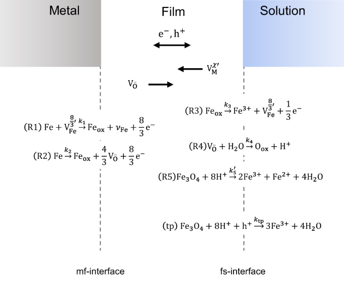
formation of the initial layer of FeO, passive film growth according to the R-PDM can occur26,27. Five interfacial reactions during stable passive film growth (Fig. 1) are assumed, which
have also been described by the PDM1. Furthermore, a sixth reaction, transpassive oxide dissolution, can occur at the film/solution interface. Additional reactions as the formation and
consumption of metal interstitials are also possible but are neglected for the purpose of this paper. Two reactions occur at the metal/film (m/f) interface: Reaction R1, the cation vacancies
(\({V}_{{\rm{Fe}}}^{8/3^{\prime} }\)) consumption (CVC), and Reaction R2, the anion vacancies (\({{\rm{V}}}_{{\rm{O}}}^{..}\)) production (AVP). Reaction 2 is a so-called non-lattice
conservative reaction because the production of oxygen vacancies and metal ions in the oxide leads to the growth of the oxide film into the metal. At the film/solution (f/s) interface, four
different reactions occur. Reaction R3, the cation vacancies production (CVP), Reaction R4, the anion vacancies consumption (AVC) and the film dissolution reaction (FDR), Reaction R5. The
FDR is also a non-lattice conservative reaction because the film dissolution moves the f/s boundary into the oxide and the film shrinks. Reaction R5 is assumed to be purely chemical and thus
potential independent. A further potential-dependent reaction describing transpassive dissolution (tp) is added to the model. This reaction is also non-lattice conservative. If all
non-lattice conservative reactions are in equilibrium—moving the interfaces equally—the system reaches a steady state. The metal is still dissolving at the m/f interface, and the film is
still dissolving at the f/s interface in a steady state, but the growth of the oxide film (by metal dissolution and oxygen vacancies production) equals the dissolution of the film at the f/s
interface. REACTION KINETICS All reactions are assumed to be irreversible, and only the oxidation paths of the reactions are included in the model. The kinetics of the reactions at the
metal/film interface can be described by the rate constants: $${k}_{{\rm{R}}i}={k}_{{\rm{R}}i}^{0{\prime} }\,{\rm{exp }}\left(\frac{{\alpha }_{{\rm{R}}i}\chi F}{{RT}}\left({\varphi
}_{{\rm{mf}}}-{\varphi }_{{\rm{eq,}}i}\right)\right)={k}_{{\rm{R}}i}^{0}\,{\rm{exp }}\left(\frac{{\alpha }_{{\rm{R}}i}\chi F}{{RT}}{\varphi }_{{\rm{mf}}}\right),\,i=1,2$$ (15)
\({k}_{i}^{0}\) is the standard reaction rate constant of the Reaction R_i_ depending on the activation energy of Reaction R_i_, _α__i_ is the charge transfer coefficient of Reaction R_i_,
_χ_ is the number of electrons involved in the reaction, _F_ the Faraday constant (96485 As/mol), _R_ the gas constant (8.314 J/mol/K) and _T_ the temperature (293 K). The potential drop at
the m/f interface _φ_mf drives the reaction. A detailed description of the potential distribution in the system is given below. The rate constants of Reaction 3 at the film/solution
interface is given by: $${k}_{{\rm{R}}3}={k}_{{\rm{R}}3}^{0}\,{\rm{exp }}\left(\frac{{\alpha }_{{\rm{R}}3}(\delta -\chi )F}{{RT}}{\varphi }_{{\rm{fs}}}\right)$$ (16) _φ_fs describes the
potential drop at the film/solution interface and _δ_ is the charge of the dissolved iron ion. Reaction 4 is a purely chemical reaction and can be described by Arrhenius law. The dissolution
of the oxide film (Reaction R5) is also assumed to be a chemical—potential independent—reaction that depends on the concentration of protons \({c}_{{{\rm{H}}}^{+}}\) at the f/s interface
and the kinetic order of film dissolution \(n\). $${k}_{{\rm{R}}5}={k}_{{\rm{R}}5}^{0}{c}_{{{\rm{H}}}^{+}}^{n}$$ (17) According to the described kinetic constants, the growth of the oxide
film can be calculated by: $$\frac{{\rm{d}}L}{{\rm{d}}t}=\Omega \left({k}_{{\rm{R}}2}-{k}_{{\rm{R}}5}\right)$$ (18) TRANSPORT EQUATIONS FOR DEFECTS INSIDE THE OXIDE The transport of the
defects can be described by the Nernst–Planck equation for the one-dimensional case along the _x_ coordinate, whereas _x_ = 0 lies at the metal/film interface:
$${J}_{i}=-{D}_{i}\frac{\partial {c}_{i}}{\partial x}-\frac{{z}_{i}F{D}_{i}}{{RT}}\frac{\partial \varphi }{\partial x}{c}_{i},\,i={\rm{OV}},{\rm{CV}}$$ (19) where _J__i_ is the flux of
species, _i_ (i.e., the oxygen vacancies and iron (cation) vacancies), _c__i_ is the concentration, _D__i_ is the diffusion coefficient of species _i_, _z__i_ is the charge of species _i_
and _φ_ is the potential. The flux, in combination with mass conservation, gives the transport equations. BOUNDARY CONDITIONS The transport of iron and oxygen vacancies (and electrons and
holes) and the boundary conditions at the interfaces are schematically represented in Fig. 2. The boundary conditions for the flux of cation (iron) vacancies \({J}_{{\rm{CV}}}(x=0)\) and
oxygen vacancies \({J}_{{\rm{OV}}}(x=0)\) at the metal/film interface are: $${J}_{{\rm{CV}}}(x=0)\,{=-k}_{{\rm{R}}1}{c}_{{\rm{CV}}}$$ (20) $${J}_{{\rm{OV}}}(x=0)\,{=k}_{{\rm{R}}2}$$ (21)
with \({c}_{{\rm{CV}}}\) the concentration of cation (iron) vacancies. The boundary conditions at the film/solution interface are: $${J}_{{\rm{CV}}}(x=L)\,{=-k}_{{\rm{R}}3}$$ (22)
$${J}_{{\rm{OV}}}\left(x=L\right){=k}_{{\rm{R}}4}{c}_{{\rm{OV}}}$$ (23) with _c_OV as the concentration of oxygen vacancies. POTENTIAL DISTRIBUTION The distribution of the potential _φ_ over
the oxide can be described by the Poisson equation for the one-dimensional case: $$\frac{{\partial }^{2}\varphi }{\partial {x}^{2}}=-\frac{\partial {F}_{{\rm{E}}}}{\partial
x}=-\frac{F}{{\varepsilon }_{{\rm{r}}}{\varepsilon }_{0}}\sum {z}_{i}{c}_{i}$$ (24) The permittivity of the vacuum _ε_0 is 8.85 × 10⁻¹² As/V/m, the relative permittivity _ε_r is material
depending, _z__i_ is the charge of the charged species, metal and oxygen vacancies (and electrons and holes in the extended model), _F_E is the elctric field strength and _c__i_ is the
concentration of the charged species at the position _x_. INTERFACE AND BOUNDARY CONDITIONS The potential distribution (across the metal, the oxide and the solution) is schematically shown
in Fig. 3a, and a detailed view of the defect layer is given in Fig. 3b. The defect layer takes into account the dimension of ions and defects. It is located between the oxide film and the
metal. It is a charge-free space with the thickness _d_dl, which is in the range of the lattice constant of the metal/metal oxide. Due to the charge-free space between the metal and the
film, the electric field is constant inside the defect layer, as can be seen by the Poisson equation. The potential drop at the metal/film interface, which drives the electrochemical
reaction at this interface, is the potential drop over the defect layer. According to the electric flux boundary condition41, the electric field strength inside the defect layer _F_E,1 and
the field strength at the film side of the defect layer/film interface _F_E,2 are connected by: $${\varepsilon }_{1}{F}_{{\rm{E}},1}={\varepsilon }_{2}{F}_{{\rm{E}},2}$$ (25) Where _ε_ is
the permittivity, \(\varepsilon ={\varepsilon }_{0}{\varepsilon }_{{\rm{r}}}\) and indices 1 and 2 represent the left-hand side and right-hand side of the interface, respectively. The
potential drop at the metal/film interface is consequently the difference between the external potential and the film potential _φ_F at this interface \({\varphi }_{{\rm{mf}}}={\varphi
}_{{\rm{ext}}}-{\varphi }_{{\rm{F}}}(x=0)\) (note that _x_ = 0 is the defect layer/film interface). The mathematical formulation of the boundary condition used in the model is in the case of
the metal/film side (note that _φ_mf and \(\partial {\varphi }_{{\rm{F}}}^{{\rm{mf}}}/\partial x\) have different signs, is one positive is the other one negative): $${\varepsilon
}_{{\rm{dl}}}\frac{\left({\varphi }_{{\rm{F}}}^{{\rm{mf}}}-{\varphi }_{{\rm{ext}}}\right)}{{d}_{{\rm{dl}}}}={\varepsilon }_{{\rm{F}}}\frac{\partial {\varphi
}_{{\rm{F}}}^{{\rm{mf}}}}{\partial x}$$ (26) where _ε_F and _ε_dl represent the permittivity of the oxide film and the defect layer, respectively. \({\varphi }_{{\rm{F}}}^{{\rm{mf}}}\) is
the potential inside the film at the metal/film interface (not a potential drop), and its (negative) partial derivation describes the electric field strength. At the film/solution interface
also, a defect layer is formed at the outer boundary of the oxide film. Subsequently, the defect layer follows the compact double layer at the solution side. It is assumed that the potential
drops completely over the compact double layer, and the potential drop inside the solution can be neglected. At these interfaces (film/defect layer, defect layer/compact layer), the
continuity of the electric flux boundary condition (Eq. 25) applies. Inside the defect layer and the compact double layer, there is no charge; thus, the electric field is constant. Since the
electric field strength inside the defect layer (_F_Edl) and the compact double layer (_F_Ecdl) is constant, the formulation of the boundary condition at the film solution interface can be
written as: $${\varepsilon }_{{\rm{F}}}\frac{\partial {\varphi }_{{\rm{F}}}^{{\rm{fs}}}}{\partial x}={\varepsilon }_{{\rm{dl}}}{F}_{{\rm{E}}}^{{\rm{dl}}}={\varepsilon
}_{{\rm{cdl}}}{F}_{{\rm{E}}}^{{\rm{cdl}}}$$ (27) where _ε_cdl is the permittivity of the compact double layer and _ε_sol of the solution. Since it is assumed that the solution potential is
0, the boundary condition can be formulated as: $$0={\varphi }_{{\rm{F}}}^{{\rm{fs}}}-{F}_{{\rm{E}}}^{{\rm{dl}}}{d}_{{\rm{dl}}}-{F}_{{\rm{E}}}^{{\rm{cdl}}}{d}_{{\rm{cdl}}}={\varphi
}_{{\rm{F}}}^{{\rm{fs}}}+\frac{{\varepsilon }_{{\rm{F}}}}{{\varepsilon }_{{\rm{dl}}}}\frac{\partial {\varphi }_{{\rm{F}}}^{{\rm{fs}}}}{\partial x}{d}_{{\rm{dl}}}+\frac{{\varepsilon
}_{{\rm{F}}}}{{\varepsilon }_{{\rm{cdl}}}}\frac{\partial {\varphi }_{{\rm{F}}}^{{\rm{fs}}}}{\partial x}{d}_{{\rm{cdl}}}$$ (28) where _d_cdl represents the thickness of the compact double
layer. TRANSPORT OF ELECTRONS AND HOLES Electrons and holes can be transported by drift due to the electric field and by diffusion due to concentration gradients42. Thus, the flux of
electrons and holes can be calculated as: $${J}_{i}=-{D}_{i}\frac{\partial {c}_{i}}{\partial x}-\frac{{z}_{i}F{D}_{i}}{{RT}}\frac{\partial \varphi }{\partial x}{c}_{i}$$ (29) with the
concentration of either electrons or holes _c__i_, the diffusion coefficient of the according charge carrier _D__i_, Faraday’s constant _F_, the universal gas constant _R_ and the universal
temperature _T_. Additional to the transport of electrons and holes, there will be a thermal generation of electrons and holes and recombination of both, which leads to the annihilation of
the charge carriers. The rate of generation and recombination _r_G can be described by43: $${r}_{{\rm{G}}}=\frac{{c}_{{\rm{e}}}{c}_{{\rm{h}}}-{c}_{i,0}^{2}}{{\tau }_{{\rm{R}}}}$$ (30) where
the indexes \({\rm{e}}\) and \({\rm{h}}\) represent electrons and holes, respectively, and \({c}_{i,0}\) the concentration of intrinsic charge carriers. The conversation of mass is given for
each species \(i\) by: $$\frac{\partial {c}_{i}}{\partial t}=-\Delta {J}_{i}+{r}_{{\rm{G}}}$$ (31) Even though it is well known that many material parameters in oxide films can be position
dependent, for example, due to impurities or high doping, which might affect the transport of the charge carriers44, for the purpose of this publication, these effects are neglected.
BOUNDARY CONDITIONS METAL/FILM INTERFACE The metal/film boundary is assumed to show ohmic behavior for the electrons, which means the electrons in the metal and in the film at the m/f
interface are in equilibrium. Assuming that the metal/film interface is a metallic junction, the Fermi level at the metal side of the boundary can be calculated by the standard potential of
the electrons \({\mu }_{{\rm{e}}}^{0}\) in the metal and the external potential _φ_ext42: $${E}_{{\rm{F}}}^{{\rm{m}}}={\mu }_{{\rm{e}}}^{0}-e{\varphi }_{{\rm{ext}}}$$ (32) Here
\({E}_{{\rm{F}}}^{{\rm{m}}}\) is the Fermi level of the electrons in the metal and _e_ the elementary charge. The concentration of electrons _c_e in the conduction band at the metal/film
interface can be calculated by43: $${c}_{{\rm{e}}}={N}_{{\rm{c}}}\,{\rm{exp }}\left(\frac{{E}_{{\rm{F}}}-{E}_{{\rm{c}}}}{{k}_{{\rm{B}}}T}\right)$$ (33) with the density of states _N__c_ in
the conduction band, the Fermi level _E__F_, the energy at the bottom edge of the conduction band _E__c_, the Boltzmann constant _k_B and the temperature _T_. Considering the equilibrium
between Fermi levels at the metal film interface \({E}_{{\rm{F}}}^{{\rm{m}}}={E}_{{\rm{F}}}^{{\rm{m}}/{\rm{f}}}\) and $${E}_{{\rm{c}}}={E}_{{\rm{c}}}^{0}-e\varphi$$ (34) where
\({E}_{{\rm{c}}}^{0}\) is a fixed value, independent of the electrical state and equal to the conduction band energy relative to vacuum. One can calculate the electrons’ concentration at the
metal film boundary as: $${c}_{{\rm{e}}}={N}_{{\rm{c}}}\,{\rm{exp }}\left(\frac{{\mu }_{{\rm{e}}}^{0}-{E}_{{\rm{c}}}^{0}+\left({\varphi }_{{\rm{F}}}^{{\rm{mf}}}-{\varphi
}_{{\rm{ext}}}\right)e}{{k}_{{\rm{B}}}T}\right)$$ (35) where \({\varphi }_{{\rm{F}}}^{{\rm{mf}}}\) is the potential at the film side of the metal/film interface, or more precisely, at the
defect layer/film interface. It is debatable that electrons and holes can enter the defect layer; for numerical simplification, the defect layer remains charge free in this study. The
calculation of holes _c_h in the valence band at the metal/film interface can be done equivalent and leads to: $${c}_{{\rm{h}}}={N}_{{\rm{v}}}\,{\rm{exp }}\left(\frac{{E}_{{\rm{v}}}^{0}-{\mu
}_{{\rm{e}}}^{0}}{{k}_{{\rm{B}}}T}\right)$$ (36) with the energy at the top edge of the valence band relative to vacuum \({E}_{{\rm{v}}}^{0}\) and the density of states of holes _N_v.
FILM/SOLUTION INTERFACE At the film/solution interface, oxidation reactions can occur which lead to the consumption of holes. The reaction rate of the oxidation gives the flux of holes at
the film/solution boundary: $${J}_{{\rm{h}}}={k}_{{\rm{tp}}}{c}_{{{\rm{h}}}^{\,+\,}}+{k}_{{{\rm{O}}}_{2}}2{c}_{{{\rm{h}}}^{\,+\,}}$$ (37) A detailed description of the reaction kinetics is
given in “Transpassive breakdown in the absence of halide ions and oxygen evolution”. BAND-TO-BAND TUNNELING Band-to-band tunneling describes the generation of an electron/holes pair due to
the tunneling of an electron from the valence band to the conduction band. This process can occur without further energy if the conduction band and the valence band edges show the same
energy at some points in the oxide. This can happen if a strong electric field leads to band bending. As shown in a previous publication26, this process only occurs at narrow band gaps and
high electric fields. Considering the band gap of iron oxide and the electric fields, this process can be neglected for the purpose of this paper. TRANSPASSIVE BREAKDOWN IN THE ABSENCE OF
HALIDE IONS AND OXYGEN EVOLUTION I propose a transpassive dissolution mechanism (in the absence of halide ions) that depends on the hole concentration and the potential drop at the
film/solution interface. If the film dissolution would only depend on the potential drop at this interface, the polarization behavior during linear polarization would drastically differ from
the polarization behavior after potential step polarization. While during linear polarization, the passive film steadily grows, there is only a small increase of the potential drop at the
f/s interface with ongoing polarization. In contrast, one can see a very high increase of the f/s potential drop after a potential step in anodic direction45 due to the (at first) thin
passive film. While the passive film grows, the potential drops at both interfaces decrease. If the transpassive dissolution only depends on the potential drop at the f/s interface, an
anodic potential step in the passive region would lead to a highly accelerated film formation and dissolution of the oxide film due to the high potential drop at both interfaces after the
potential step. In contrast, one sees only an accelerated film formation after a potential step45,46. For accelerated film dissolution, both sufficient f/s potential drop and holes
concentration must be given. The proposed reaction equation in case of the dissolution of \({\rm{F}}{{\rm{e}}}_{3}{{\rm{O}}}_{4}\) can be written as:
$${{\rm{Fe}}}_{3}{{\rm{O}}}_{4}+8{{\rm{H}}}^{+}+{{\rm{h}}}^{+}\to 3{{\rm{Fe}}}^{3+}+4{{\rm{H}}}_{2}{\rm{O}}$$ (38) while the reaction kinetic is formulated as:
$${k}_{{\rm{tp}}}={k}_{{\rm{tp}}}^{0}{c}_{{{\rm{h}}}^{\,+\,}}{\rm{exp }}\left(\frac{{\alpha }_{{\rm{tp}}}F}{{RT}}{\varphi }_{{\rm{fs}}}\right)$$ (39) Accordingly, the flux of holes from the
film toward the solution must be added to the boundary condition for the hole concentration. This leads to a flux boundary condition depending on the hole concentration and the potential
drop at the f/s interface in case of holes. The transpassive dissolution products can form a porous film on the electrode surface. The formation of this unstable transpassive film is
neglected in the current form of the model. In the presence of halide ions, additional different passive breakdown mechanisms can be considered47,48,49,50. Due to the experimental nature
(polarization in borate buffer without halide ions), these breakdown mechanisms are not considered. The formation of oxygen is given by: $${{\rm{H}}}_{2}{\rm{O}}+2{{\rm{h}}}^{+}\to
\frac{1}{2}{{\rm{O}}}_{2}+2{{\rm{H}}}^{+}$$ (40) and the rate constant can be formulated as: $${k}_{{{\rm{O}}}_{2}}={k}_{{{\rm{O}}}_{2}}^{0}\,{\rm{exp }}\left(\frac{{\alpha
}_{{{\rm{O}}}_{2}}2F}{{RT}}\left({\varphi }_{{\rm{ext}}}-{\varphi }_{{\rm{eq}}}^{{{\rm{O}}}_{2}}\right)\right)$$ (41) RESULTS AND DISCUSSION POLARIZATION MEASUREMENTS AND SIMULATIONS The
intention of the presented model is to develop a tool which can describe oxide film formation, growth and dissolution. A model which is capable of simulating these processes can be used to
predict the corrosion behavior of various passivated metals. All three stages of passive film growth, the onset of passivation, stable growth and dissolution, can be seen during polarization
scans in the passivating environment. Therefore, polarization scans of an iron electrode are performed in borate buffer (pH 8.4) containing 0.01 M EDTA (experimental details see “Methods”)
and are compared to the simulation. The polarization scans of the iron electrode show typical and reported behavior (Fig. 4a, b)16. The dynamic polarization scan shows a cathodic branch,
which corresponds to the hydrogen formation at −1.2 to −0.8 V. The cathodic branch is followed by the active dissolution of iron to Fe3+ and active/passive transition due to the formation of
iron hydroxides, their adsorption, oxidation and formation of iron oxide (compare “Active dissolution and active passive transition”). The dissolution of iron, followed by the initial
growth of the iron oxide layer, leads to an anodic current peak in the active/passive region. A second anodic peak is visible, which probably results from the oxidation of dissolved Fe2+ to
Fe3+16. The disappearance of the second oxidation peak in stirred electrolyte and in the case of static polarization (Fig. 4b) supports the hypothesis of oxidizing dissolved Fe2+ to Fe3+.
The oxidation peaks are followed by a nearly constant current from 0 to around 1.0 V, during which stable growth of the passive film occurs. Further increasing the potential results in a
steep increase of current due to the oxygen evolution and transpassive dissolution of the film. The calculated polarization curve (parameters given in the Supplementary Material) shows very
similar behavior to the experiment (Fig. 4c). The simulation matches the experiments in the four different polarization regions (hydrogen formation, active/passive transition, passive region
and transpassive region). Especially, the nearly constant current in the passive region fits theory and experiments. Nevertheless, the simulated passive current during polarization is lower
compared to the experiments. Both the simulated steady-state film thickness and the polarization currents show a very good match to the polarization measurements and measured film thickness
(Fig. 4d). The film thickness of the iron oxide is derived by impedance measurements and Equivalent Electrical Circuit fitting. Both the impedance data and the fitting parameters are given
in the Supplementary Material (Bode plots of EIS data: Supplementary Fig. 1, Equivalent Electrical Circuit used to fit data: Supplementary Fig. 2). The theory of stable passive film growth
proposes a constant polarization current during passive film growth. This constant steady-state polarization current can be seen during the measurements and the calculation (Fig. 4d). After
stable passive film growth, at the onset potential of increased transpassive dissolution, an increasing polarization current is noticeable. This is due to the accelerated electrochemical
film dissolution, which is accompanied by accelerated film formation (due to the thinning of the passive layer) and oxygen evolution. Both the calculated and measured polarization currents
increase. The calculation (with the given parameters) overestimates the polarization current at 1.0 V in comparison to the measurement. The steady-state film thickness increases linearly
with the polarization potential over a broad potential range, which is in accordance with the literature51,52. At a polarization potential of 1.0 V, one can observe a steep decrease in the
steady-state film thickness due to transpassive dissolution. At even higher anodic potentials, the protecting passive film is destroyed, and corrosion of the metal is noticeable, as can be
seen by a microscope image of the iron electrode taken after polarization (compare Supplementary Fig. 3). In 1976, Sato et al. could show by ellipsometry measurements that the barrier film
does not further linearly grow in the transpassive region51. This finding is in accordance with our calculations. In contrast to our modeling approach and the EIS measurements (data shown in
the Supplementary Material, experimental details given in “Methods”), Sato et al. predicted a constant film thickness of the barrier layer film in the transpassive region. Unfortunately,
they only took one film thickness measurement at a transpassive potential. Both our EIS measurements and the microscopy measurements clearly show that the film does not remain constant but
eventually breaks, which leads to corrosion of the underlying iron. It should be noted that a steady state was reached after polarization for several hours (10 h and more) in the case of the
simulation, whereas in the case of the experiments after 2 h of polarization, no change of current was visible, which indicates a steady state. This suggests that the modeled reactions,
while a steady state is not yet reached, are slow compared to reality. This might be an explanation for the lower passive current during dynamic polarization (Fig. 4c). STEADY-STATE BEHAVIOR
OF IRON OXIDE Modeling the oxide film growth allows insights into oxide film parameters under different conditions. Electric field strength, vacancies concentrations and interfacial
potentials play an important role in the behavior of the oxide film and has been investigated for steady-state conditions after static polarizations. The electric field strength in the oxide
film after the steady state is reached is nearly potential independent but shows a strong dependency regarding the position inside the oxide (Fig. 5a). A potential-independent electric
field strength is in agreement with the original PDM hypothesis. A previous publication showed this must not be the case but seems to depend on the model parameters26,27. In contrast to the
original PDM, we observe a strong dependency of the electric field strength on the position inside the film. At the metal/film and the film/solution interface, the field strength shows
negative (m/f interface) or low (f/s interface) values compared to the oxide bulk. It should be noted that the field strength at the m/f interface is given by the steady-state condition:
$${k}_{2}^{0}\,{\rm{exp }}\left(\frac{\alpha {nF}}{{RT}}{\varphi }_{{\rm{mf}}}\right)={k}_{5}$$ (42) in combination with the calculation of the potential drop at the metal/film interface:
$${\varphi }_{{\rm{mf}}}={F}_{{\rm{E}},{\rm{mf}}}{d}_{{\rm{dl}}}$$ (43) and the electric flux boundary condition: $${\varepsilon }_{{\rm{dl}}}{F}_{{\rm{E}},{\rm{dl}}}={\varepsilon
}_{{\rm{F}}}{F}_{{\rm{E}},{\rm{F}}}(x=0)$$ (44) The potential drop is given as: $${\varphi }_{{\rm{mf}}}={\rm{ln}}\left(\frac{{k}_{5}}{{k}_{2}^{0}}\right)\frac{{RT}}{\alpha {nF}}\,$$ (45)
which leads to the electric field strength \({F}_{{\rm{E}},{\rm{F}}}(x=0)\) at the m/f interface: $${F}_{{\rm{E}},{\rm{F}}}\left(x=0\right)=\frac{{\varepsilon }_{{\rm{dl}}}}{{\varepsilon
}_{{\rm{F}}}}\frac{{\varphi }_{{\rm{mf}}}}{{d}_{{\rm{dl}}}}=\frac{{\varepsilon }_{{\rm{dl}}}}{{\varepsilon }_{{\rm{F}}}}{\rm{ln}}\left(\frac{{k}_{5}}{{k}_{2}^{0}}\right)\frac{{RT}}{\alpha
{nF}}\frac{1}{{d}_{{\rm{dl}}}}\,\approx \,-0.5\times {10}^{8}{{\rm{Vm}}}^{-1}$$ (46) From this, it becomes clear that the field strength at the m/f interface depends on the ratio of
\({k}_{2}^{0}/{k}_{5}\). A constant field strength at the m/f interface, which equals the field strength in the middle of the oxide bulk, would need a rate constant ratio of (assuming a bulk
field strength of \({F}_{{\rm{E}},{\rm{F}}}=1\times {10}^{8}{{\rm{Vm}}}^{-1}\,\)): $$\frac{{k}_{5}}{{k}_{2}^{0}}=\,{\rm{exp }}\left(\frac{{\varepsilon }_{{\rm{F}}}}{{\varepsilon
}_{{\rm{dl}}}}{F}_{{\rm{E}},{\rm{F}}}(x=0)\frac{\alpha {nF}}{{RT}}{d}_{{\rm{dl}}}\right)\approx {1.4\times 10}^{5}$$ (47) In contrast, the maximum field strength inside the bulk oxide
differs by around 1% between 0.0 and 0.8 V, whereas the field strength has its maximum at 0.4 V (Fig. 5b). Assuming the small deviations, the field strength can be assumed as potential
independent. Nevertheless, the strong dependency on the spatial coordinate influences the vacancies transport and thus the reaction rate. The profiles of the vacancy concentrations at
different polarization potentials after reaching a steady state show nearly no difference toward the polarization potential (Fig. 6). Anion vacancies show a high concentration at the
metal/film interface at which they are formed, a nearly constant concentration within the oxide film and a low concentration at the film/solution interface at which they are consumed. The
concentration profile of the cation vacancies is showing a low concentration at the metal/film interface (consumption of cation vacancies) and a high concentration at the film/solution
interface (production of cation vacancies). The concentration of anion vacancies is higher compared to the concentration of cation vacancies (Fig. 6), which is in agreement with the n-doped
nature of iron oxide. The interfacial potentials at the metal/film and film/solution interface are still a matter of debate. As mentioned earlier, the original PDM states a potential
independent metal/film potential and a linear dependency of the film/solution potential on the external potential22. High field models, in contrast, suggest both interfacial potentials to be
independent of the external potential after the steady state is reached (at least in the passive region)53. The calculations show that directly after a potential step, the interfacial
potentials increase. While the system reaches a steady state, the interfacial potentials decrease toward a constant value (Fig. 7a), which is in agreement with the high field model. Both
interfacial potentials, _φ_mf and _φ_fs are nearly potential independent after reaching a steady state (Fig. 7b). In the case of the metal/film potential, the steady state conditions dictate
the potential to be constant within the passive range because _k_2 must equal _k_5 and _k_5 is considered to be potential independent (which is an assumption made). The steady-state
film/solution potential shows no dependency on the applied potential as well (Fig. 7b). In our previous publication, we found a very weak dependency of the film/solution potential on the
external potential26. Thus, the dependency of the film solution potential on the applied potential seems to be parameter dependent. Furthermore, the addition of electrons and holes (which
are not included in the steady state case between 0.0 and 0.8 V) can have a huge impact on the potential distribution27 and thus the interfacial potential. Therefore, additional calculations
need to be performed to gain deeper insight into the behavior of the film/solution potential. DYNAMIC BEHAVIOR In contrast to the steady state behavior described above, during dynamic
polarization, the system is far from a steady state. Thus, the film has not reached its steady state thickness, and the higher external potential cannot be balanced by a thicker oxide film.
This leads to strong dependencies of the film properties on the external potential. With the onset of passive film growth during dynamic polarization, the film starts to thicken slowly and,
after a while, reaches a region of nearly linear film growth with increasing potential. After reaching higher anodic potentials, above 1.0 V, the film starts to dissolve due to transpassive
dissolution, and the film thickness decreases (Fig. 8a). The overall film thickness is significantly lower compared to the steady state film thickness because the film has less time to form.
Both interfacial potentials increase during dynamic polarization (Fig. 8b), whereas the film/solution potential increases faster compared to the metal/film potential drop. With beginning
transpassive film dissolution (1.0 V), both potentials start to increase with a steeper slope, leading to accelerated interfacial reactions. With increasing potential during dynamic
polarization, the electric field also increases (Fig. 8c). This can be explained by the fact that the oxide film has not reached its steady state thickness, and the higher external potential
drops over a very thin oxide film. Thus, the electric field is significantly higher compared to the electric field strength at a steady state (Fig. 5). The concentration of defects (Fig. 9)
and holes (Fig. 10) also increases with increasing external potential during dynamic polarization. In the case of iron and oxygen defects, the increasing concentration can be explained by
the accelerated interfacial reactions due to the increasing interfacial potential drops. The concentration of holes does only slightly increase with increasing potential (Fig. 10). On the
one hand, the higher electric field leads to higher transport of holes toward the film/solution interface. This, in combination with the assumption of ohmic behavior at the metal/film
boundary (Dirichlet boundary condition), leads to an increasing holes concentration. On the other hand, with increasing film/solution potential, the holes consumption by the oxygen evolution
and the transpassive dissolution also increase. Both, in combination, lead to a slightly increasing holes concentration. DISCUSSION The R-PDM could successfully model the full polarization
behavior of an iron electrode in borate buffer. The active/passive transition, the passive region and the transpassive region could be modeled with good agreement with the measurements.
Furthermore, we successfully introduced a transpassive dissolution mechanism for metal oxides under anodic polarization in the absence of halide ions. The main findings of the simulations
are: * Very good agreement between experiments and simulation for both static and dynamic polarization scans of iron electrodes. * Passive film thickness increases linearly with increasing
potential during stable passive film growth. * The electric field strength is not constant over the film. * The maximum electric field strength only differs by 1% over the range of 0.8 V.
The dependency of the electric field on the external potential seems to be parameter-dependent and can be neglected in this case (however, our previous publications could show that this
dependency can be more pronounced26,27). * During static polarization, the potential drop at the film/solution interface is nearly potential independent. This matches the high field
assumptions. Nevertheless, the behavior of the film/solution potential drop needs to be further investigated, among others, the impact of electrons and holes on the potential drop. * During
dynamic polarization, the potential drop at the film/solution interface increases steadily with increasing potential. Although a full polarization scan of an iron electrode in a neutral
halide-free environment could be successfully modeled, in most real-life applications, breakdown due to anodic dissolution will not be the case, but film breakdown due to local corrosion.
Thus, to model the behavior of oxide films in many practical applications, a breakdown mechanism leading to pitting corrosion involving the role of halide ions must be added to the model,
which is currently under development. METHODS EXPERIMENTAL DETAILS All electrochemical tests were performed in a three-electrode setup with an iron electrode as working electrode (purity
99.99 %) with a diameter of 2 mm, a platinum counter electrode and an Ag/AgCl (3 M KCl) reference electrode. All potentials in this paper are referred to the Ag/AgCl reference electrode. The
electrochemical tests were performed with an Autolab PGSTAT128N potentiostat with the FRA32 module for impedance measurements. All tests were conducted in 0.1 M borate buffer (pH 8.4)
containing 0.01 M ethylenediaminetetraacetic Acid (EDTA). The dynamic polarization tests were performed with a scan rate of 5 mV/s from −1.2 V to 1.2 V. The static polarization tests were
performed by stepwise increasing the potential in anodic direction and holding the potential for 7200 s. The impedance measurements were performed after the polarization measurements (at the
polarization potential) in a frequency range from 105 Hz down to 10−2 Hz, applying a voltage amplitude from 10 mV (rms). NUMERICAL DETAILS The system of differential equations for the
transport of charged species and the calculation of the potential distribution is discretized using the finite elements method. The simulation has been performed using the software COMSOL
Multiphysics and the package Mathematics within the software. For the simulation, a mesh containing 80 nodes with finer mesh toward the boundaries has been used. Within COMSOL, the Deformed
Geometry with Prescribed Mesh Velocity has been used to model the growth of the film. Considering the non-lattice conservative reactions (2, 5 & tp), both boundaries, the metal film
boundary and the film solution boundary would move. This can also be represented by the movement of only one boundary, which moves with the difference of both boundary velocities. To
stabilize the simulation, the polarization curve has been separated into two parts. The first case contains the active dissolution, active/passive transition and formation of the initial
oxide layer on the metal surface. Afterward, in the second case, the stable growth of the passive film in the passive region as well as the transpassive dissolution, which is accompanied by
oxygen evolution, are modeled. The potentials of the simulation have been shifted by −0.4 V after calculation to fit the measurements (considering the relative nature of potentials, this
does not alter the results). To simplify the model and to increase numerical stability, the concentration of electrons and holes has been neglected during static polarization between 0 and
0.8 V. The number of electrons and holes is very small compared to the defect concentration; thus, the impact on the Poisson equation is neglectable. Furthermore, holes only play a role
during transpassive dissolution. In the case of higher potentials (above 0.8 V) and in the case of the whole dynamic polarization curve, holes have been added to the model. However, holes
have been neglected for the solution of the Poisson equation. This approach is reasonable since the number of holes is several orders of magnitude smaller compared to the defect
concentration. The model parameter has been adjusted to fit the experimental data. It is important to note that the model might be overdetermined for the given data set. This means there are
probably more parameter combinations possible to fit the experimental data. Thus, the value of the single parameters does not necessarily reflect the real physical values. The aim of this
paper is to present the model, to show the benefits and power of the model and to give general insights into dynamic oxide film growth and breakdown. It is not the aim of the paper to
present physically reasonable values for the iron oxide formation. To ensure physically reasonable parameters by fitting the model to experimental data, a broader set of experimental data is
necessary. This can be done by dynamic impedance spectroscopy54,55 and by simulation of the impedance behavior by the model. A parameter fit of the model to dynamic impedance measurements
is currently under development. DATA AVAILABILITY The data that support the findings of this study are available from the corresponding author upon reasonable request. CODE AVAILABILITY
Parts of the code can be found at https://doi.org/10.13140/RG.2.2.33316.76160 (e.g., available at researchgate.com). The full code is available from the corresponding author upon reasonable
request. REFERENCES * Macdonald, D. D. On the existence of our metals-based civilization. _J. Electrochem. Soc._ 153, B213 (2006). Article CAS Google Scholar * Tomashov, N. D. &
Chernova, G. P. In _Passivity and Protection of Metals Against Corrosion_, Vol. 1, 9–53 (Springer, 1967). * Keir, J. Experiments and observations on the dissolution of metals in acids, and
their precipitations; with an account of a new compound acid menstruum, useful in some technical operations of parting metals. _Phil. Trans. R. Soc_. 80, 359–384 (1790). Article Google
Scholar * Schönbein, C. F. Über das Verhalten des Zinns und des Eisens gegen die Salpetersäure. _Ann. Phys_. 113, 390–399 (1836). Article Google Scholar * Bösing, I. A. _Effects of
Material Treatments on Growth Kinetics of Passive Films on Steel Alloys_. PhD thesis, University of Bremen (2020). * Uhlig, H. H. Passivity in metals and alloys. _Corros. Sci._ 19, 777–791
(1979). Article CAS Google Scholar * Sato, N. & Cohen, M. The kinetics of anodic oxidation of iron in neutral solution. _J. Electrochem. Soc._ 111, 512 (1964). Article CAS Google
Scholar * Nagayama, M. & Cohen, M. The anodic oxidation of iron in a neutral solution: I. The nature and composition of the passive film. _J. Electrochem. Soc._ 109, 781–790 (1962).
Article CAS Google Scholar * Russell, P. & Newman, J. Anodic dissolution of iron in acidic sulfate electrolytes II. Mathematical model of current oscillations observed under
potentiostatic conditions. _J. Electrochem. Soc._ 134, 1051–1059 (1987). Article Google Scholar * Russell, P. & Newman, J. Anodic dissolution of iron in acidic sulfate electrolytes I.
Formation and growth of a porous salt film. _J. Electrochem. Soc._ 133, 59–69 (1986). Article CAS Google Scholar * Orlik, M. In _Self-Organization in Electrochemical Systems I_,
_Monographs in electrochemistry_, Vol. 1 (ed. Scholz, F.) Ch. 6.1, 425–500 (Springer, 2012). * Ahn, S., Kwon, H. & Macdonald, D. D. Role of chloride ion in passivity breakdown on iron
and nickel. _J. Electrochem. Soc._ 152, B482 (2005). Article Google Scholar * Veluchamy, A., Sherwood, D., Emmanuel, B. & Cole, I. S. Critical review on the passive film formation and
breakdown on iron electrode and the models for the mechanisms underlying passivity. _J. Electroanal. Chem._ 785, 196–215 (2017). Article CAS Google Scholar * DorMohammadi, H., Pang, Q.,
Árnadóttir, L. & Burkan Isgor, O. Atomistic simulation of initial stages of iron corrosion in pure water using reactive molecular dynamics. _Comput. Mater. Sci._ 145, 126–133 (2018).
Article CAS Google Scholar * DorMohammadi, H., Pang, Q., Murkute, P., Árnadóttir, L. & Burkan Isgor, O. Investigation of iron passivity in highly alkaline media using reactive-force
field molecular dynamics. _Corros. Sci._ 157, 31–40 (2019). Article CAS Google Scholar * Sikora, E. & Macdonald, D. D. The passivity of iron in the presence of
ethylenediaminetetraacetic acid I. General electrochemical behavior. _J. Electrochem. Soc._ 147, 4087–4092 (2000). Article CAS Google Scholar * Azumi, K., Ohtsuka, T. & Sato, N.
Mott-Schottky plot of the passive film formed on iron in neutral borate and phosphate solutions. _J. Electrochem. Soc._ 134, 1352–1357 (1987). Article CAS Google Scholar * Marcus, P.
_Corrosion Mechanism in Theory and Practice_ (Marcel Dekker, 2002). * Cabrera, N. & Mott, N. F. Theory of the oxidation of metals. _Rep. Prog. Phys._ 12, 163–184 (1949). Article CAS
Google Scholar * Fehlner, F. P. Low-temperature oxidation. _Philos. Mag. B_ 55, 633–636 (1987). Article CAS Google Scholar * Chao, C. Y., Lin, L. F. & Macdonald, D. D. A point defect
model for anodic passive films. _J. Electrochem. Soc._ 128, 1187–1194 (1981). Article CAS Google Scholar * Macdonald, D. D. The point defect model for the passive state. _J. Electrochem.
Soc._ 139, 3434–3449 (1992). Article CAS Google Scholar * MacDonald, D. D. The history of the Point Defect Model for the passive state: a brief review of film growth aspects.
_Electrochim. Acta_ 56, 1761–1772 (2011). Article CAS Google Scholar * Macdonald, D. & Engelhardt, G. The Point Defect Model for bi-layer passive films. _ECS Trans._ 28, 123–144
(2010). Article CAS Google Scholar * Battaglia, V. & Newman, J. Modeling of a growing oxide film: the iron/iron oxide system. _J. Electrochem. Soc._ 142, 1423 (1995). Article CAS
Google Scholar * Bösing, I., La Mantia, F. & Thöming, J. Modeling of electrochemical oxide film growth-a PDM refinement. _Electrochim. Acta_. 406, 139847 (2022). Article Google Scholar
* Bösing, I., Thöming, J. & La Mantia, F. Modeling of electrochemical oxide film growth-impact of band-to-band tunneling. _Electrochim. Acta_ 406, 139848 (2022). Article Google
Scholar * Bösing, I., Marquardt, G. & Thöming, J. Effect of heat treatment of martensitic stainless steel on passive layer growth kinetics studied by electrochemical impedance
spectroscopy in conjunction with the Point Defect Model. _Corros. Mater. Degrad._ 1, 77–91 (2020). Article Google Scholar * Vankeerberghen, M. 1D steady-state finite-element modelling of a
bi-carrier one-layer oxide film. _Corros. Sci._ 48, 3609–3628 (2006). Article CAS Google Scholar * Samin, A. J. & Taylor, C. D. A one-dimensional time-dependent model for studying
oxide film growth on metallic surfaces. _J. Appl. Phys_. 123, 245303 (2018). Article Google Scholar * Albu, C. et al. Influence of the applied potential and pH on the steady-state behavior
of the iron oxide. _Electrochim. Acta_ 67, 119–126 (2012). Article CAS Google Scholar * Bataillon, C. et al. Corrosion modelling of iron based alloy in nuclear waste repository.
_Electrochim. Acta_ 55, 4451–4467 (2010). Article CAS Google Scholar * Seyeux, A., Maurice, V. & Marcus, P. Oxide film growth kinetics on metals and alloys: I. Physical model. _J.
Electrochem. Soc._ 160, C189–C196 (2013). Article CAS Google Scholar * Geringer, J. & MacDonald, D. D. Modeling fretting-corrosion wear of 316L SS against poly(methyl methacrylate)
with the Point Defect Model: fundamental theory, assessment, and outlook. _Electrochim. Acta_ 79, 17–30 (2012). Article CAS Google Scholar * Fattah-alhosseini, A. & Attarzadeh, N. The
mechanism of transpassive dissolution of AISI 321 stainless steel in sulphuric acid solution. _Int. J. Electrochem._ 2011, 1–9 (2011). Google Scholar * Betova, I., Bojinov, M. &
Tzvetkoff, T. Transpassive dissolution mechanism of ferrous alloys in phosphoric acid/acetic acid mixtures. _J. Solid State Electrochem._ 9, 154–167 (2005). Article CAS Google Scholar *
Fattah-alhosseini, A., Saatchi, A., Golozar, M. A. & Raeissi, K. The transpassive dissolution mechanism of 316L stainless steel. _Electrochim. Acta_ 54, 3645–3650 (2009). Article CAS
Google Scholar * Gerischer, H. Über den ablauf von redoxreaktionen an metallen und an halbleitern I. Allgemeines zum elektronenübergang zwischen einem festkörper und einem
redoxelektrolyten. _Z. Phys. Chem. NF_ 26, 223–247 (1960). Article CAS Google Scholar * Gerischer, H. Über den ablauf von redoxreaktionen an metallen und an halbleitern III.
Halbleiterelektroden. _Z. Phys. Chem. NF_ 27, 49–79 (1961). Article Google Scholar * Misawa, T., Hashimoto, K. & Shimodaira, S. The mechanism of formation of iron oxide and iron
hydroxides in aqueous solution at room temperature. _Corros. Sci_. 14, 131–149 (1974). Article CAS Google Scholar * Ellingson, S. W. _Electromagnetics_, Vol. 1 (VT, 2018). * Newman, J.
& Thomas-Alyea, K. E. _Electrochemical Systems_ (Wiley, 2012). * Thuselt, F. _Physik der Halbleiterbauelemente_ (Springer, 2011). * Marshak, A. H. Modeling semiconductor devices with
position-dependent material parameters. _IEEE Trans. Electron. Devices_ 36, 1764–1772 (1989). Article Google Scholar * Olsson, C.-O. A., Hamm, D. & Landolt, D. Evaluation of passive
film growth models with the electrochemical quartz crystal microbalance on PVD deposited Cr. _J. Electrochem. Soc._ 147, 4093 (2002). Article Google Scholar * Schmutz, P. & Landolt, D.
Electrochemical quartz crystal microbalance study of the transient response of passive Fe-25Cr alloy. _Electrochim. Acta_ 45, 899–911 (1999). Article CAS Google Scholar * Frankel, G.
Pitting corrosion of metals. _J. Electrochem. Soc._ 145, 2186 (1998). Article CAS Google Scholar * Metikoš-Huković, M., Grubač, Z. & Omanovic, S. Change of n-type to p-type
conductivity of the semiconductor passive film on N-steel: enhancement of the pitting corrosion resistance. _J. Serbian Chem. Soc._ 78, 2053–2067 (2013). Article Google Scholar * Marcus,
P., Maurice, V. & Strehblow, H. H. Localized corrosion (pitting): a model of passivity breakdown including the role of the oxide layer nanostructure. _Corros. Sci._ 50, 2698–2704 (2008).
Article CAS Google Scholar * Soltis, J. Passivity breakdown, pit initiation and propagation of pits in metallic materials: review. _Corros. Sci._ 90, 5–22 (2015). Article CAS Google
Scholar * Sato, N., Kudo, K. & Nishimura, R. Depth analysis of passive films on iron in neutral borate solution. _J. Electrochem. Soc._ 123, 1419–1423 (1976). Article CAS Google
Scholar * Sato, N., Noda, T. & Kuw, K. Thickness and structure of passive films in iron in acidic and basic solution. _Electrochim. Acta_ 19, 471–475 (1974). Article CAS Google
Scholar * Lohrengel, M. M. Thin anodic oxide layers on aluminium and other valve metals: high field regime. _Mater. Sci. Eng. R Rep._ 11, 243–294 (1993). Article Google Scholar *
Battistel, A. & la Mantia, F. On the physical definition of dynamic impedance: how to design an optimal strategy for data extraction. _Electrochim. Acta_ 304, 513–520 (2019). Article
CAS Google Scholar * Koster, D., Du, G., Battistel, A. & la Mantia, F. Dynamic impedance spectroscopy using dynamic multi-frequency analysis: A theoretical and experimental
investigation. _Electrochim. Acta_ 246, 553–563 (2017). Article CAS Google Scholar Download references ACKNOWLEDGEMENTS I would like to thank Fabio La Mantia and Jorg Thöming for their
support and fruitful discussions during the preparation of this work. Furthermore, I would like to thank Alexander Fuchs for pointing out inaccuracies in the previous model description. This
study received no funding. FUNDING Open Access funding enabled and organized by Projekt DEAL. AUTHOR INFORMATION AUTHORS AND AFFILIATIONS * Chemical Process Engineering Group (CVT),
University of Bremen, Leobener Straße 6, 28359, Bremen, Germany Ingmar Bösing Authors * Ingmar Bösing View author publications You can also search for this author inPubMed Google Scholar
CONTRIBUTIONS I.B. performed the experiments, wrote the code and interpreted the results of the experiments and simulations, wrote the manuscript and made the figures. CORRESPONDING AUTHOR
Correspondence to Ingmar Bösing. ETHICS DECLARATIONS COMPETING INTERESTS The author declares no competing interests. ADDITIONAL INFORMATION PUBLISHER’S NOTE Springer Nature remains neutral
with regard to jurisdictional claims in published maps and institutional affiliations. SUPPLEMENTARY INFORMATION SUPPLEMENTARY MATERIAL RIGHTS AND PERMISSIONS OPEN ACCESS This article is
licensed under a Creative Commons Attribution 4.0 International License, which permits use, sharing, adaptation, distribution and reproduction in any medium or format, as long as you give
appropriate credit to the original author(s) and the source, provide a link to the Creative Commons license, and indicate if changes were made. The images or other third party material in
this article are included in the article’s Creative Commons license, unless indicated otherwise in a credit line to the material. If material is not included in the article’s Creative
Commons license and your intended use is not permitted by statutory regulation or exceeds the permitted use, you will need to obtain permission directly from the copyright holder. To view a
copy of this license, visit http://creativecommons.org/licenses/by/4.0/. Reprints and permissions ABOUT THIS ARTICLE CITE THIS ARTICLE Bösing, I. Modeling electrochemical oxide film
growth—passive and transpassive behavior of iron electrodes in halide-free solution. _npj Mater Degrad_ 7, 53 (2023). https://doi.org/10.1038/s41529-023-00369-y Download citation * Received:
14 March 2023 * Accepted: 26 May 2023 * Published: 28 June 2023 * DOI: https://doi.org/10.1038/s41529-023-00369-y SHARE THIS ARTICLE Anyone you share the following link with will be able to
read this content: Get shareable link Sorry, a shareable link is not currently available for this article. Copy to clipboard Provided by the Springer Nature SharedIt content-sharing
initiative